
Harmon Rocket II Blueprint Notes
The editing of this page is ongoing. Please E-mail any suggestion or building tip.
The following stuff is mostly applicable to the Harmon Rocket II. It won't as helpful to F-1 builders! But I'm adding more stuff constantly, so check back once in a while.
You might want to print this stuff out so you can take it out to the shop and update your blueprints with the items that you deem worthy of changing, if any! You may not feel the need to do all these things. So far, I've found most, BUT NOT ALL, of them to be sound ideas for what I want from my airplane.
Keep in mind that this stuff is gleaned from various sources, some reliable and some ???? Use your best judgment. If that doesn't work, just whip out the Master Card and buy new metal until you get it right! Then drop me a note so I can add your experiences to this page and change anything that might be misleading.
Errors, omissions, and suggestions to improve (or complicate?) John Harmon's plans:
This stuff is tough to describe, but I can't find a scanner big enough to copy the blueprints! A picture is worth a thousand words... well, for now you just get the thousand words! I'll try to add a few photos of my stuff as I build.
Most of these changes came from a well-known Texan, Mark Frederick, who has built several HRII's. Most of the items you can figure out or find on Van's drawings, but this might help to speed the process. NOTE: According to John Harmon many of the changes that Mark suggests relating to the fuselage width are to make the sliding canopy installation easier. So, if you're building a flopper, like I am, take this under advisement.
Gear Legs:
I'm not sure where to put these notes since there isn't a print directly corresponding to the gear legs.
I was very surprised to find out that John Harmon has a newer model of gear legs that I had no clue existed until last Tuesday (9/11/01). There seem to be 3 styles that I know of. All are 2.5" diameter. I think 2.5" is correct, nonetheless, they all seem the same except for the machining of the part that goes into the engine mount socket. Here's what I've seen, but it is possible that John Harmon has other mods I haven't seen:1) the oldest ones are machined with a square notch at the base of the engine mount socket. These are known "breakers" to be modified before use. It seems that they would crack at the notch, particularly if the notched edge was leveraging itself against the engine mount socket.
2) These are identical to #1 except that the square notch has been changed to a large (18"?) radius to eliminate the stress concentration. I haven't heard of any problems with this setup and several "experts" and multiple HRII builders say to use them without fear.
3) The newest ones are machined to fit a very slightly (~1/8") larger diameter engine mount socket. These will not interchange with #1 or #2.
So, that's everything that I know about them. Let me know if you find out anything else, I certainly don't want to mislead anyone about this important topic. After all, nobody wants a retractable gear HRII!
Drawing # 104, vertical stabilizer & rudder:
No problems here. The only things different than Van's drawings are the 2" dimension under the leading edge of the VS and the way John has you close the leading edges of the rudder and elevator. I closed mine per the Van's drawing as I felt it was less likely to cause a rubbing problem against the VS or HS.
For those of you using other than an RV-4 tail.... you're on your own here.
HERE'S A NOTE FROM HOBIE REGARDING THE TAIL CONSTRUCTION:
Drawing # 109, wing layout:
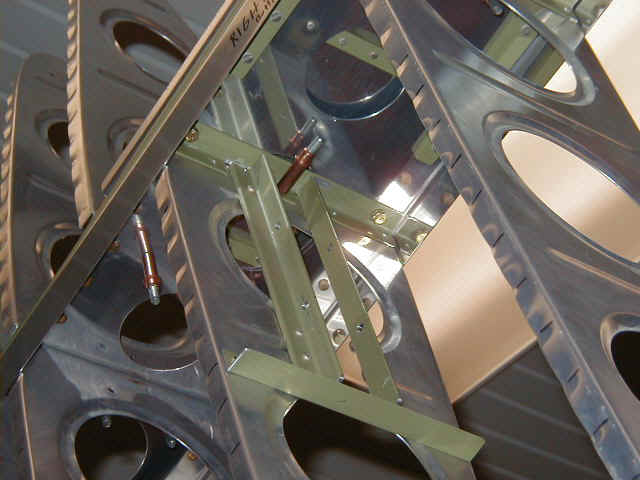
Overall this one's OK, but Mark recommends reversing the aileron bellcrank rib, W-11L, so the flanges point inboard. This might ease installation of the aileron bellcrank support angles.
I didn't fully grasp the implications of this suggestion until I added the aileron bellcrank support angles and realized that they were going to interfere with the stiffener attached to the spar. There are a couple photos of my solution below. It's difficult to see but if you look really close at the left photo you can see the stiffener that bolts to the spar has two notches to clear the aileron bellcrank support angles. The right photo shows the doubler that was added on the opposite side to strengthen the spar stiffener.
Also, you might want to consider making a note on this sheet to leave about 3/4" of skin overhang at the wingtip. Van calls for a measly 1/2" overhang. The extra overhang will greatly simplify the installation of your wingtips later. You can always trim it off later if you don't need it. The main skins are no problem here. However, the leading edge skins, including the tank skins, when shifted outboard slightly can cause a minor edge distance problem at the outboard tank joint since the leading edge skin edge will fall right on the bend in the rib. Since that area is a butt joint it really isn't a problem, just be careful and not shift them too far outboard.
Drawing # 111, wing spar webs:
Van's parts don't always exactly match John's drawings. The dimensions below are approximate and are measured from the butt end of the spar unless I misread my notes (It's your responsibility to double check and make sure I don't mislead you!). Don't be surprised if they don't match your spar exactly.
You'll notice that Van's RV-4 spar webs have two extra lightening holes compared to Harmon's drawing. Hmmmm, hard to change that. This will slightly impact the inboard leading edge rib (not the tank ribs) at sta. 71 1/2. I attached that rib to the web with 2 rivets. That rib also gets riveted to a stiffener, which is bolted in place. No big problems. The extra lightening holes also cause the aileron bellcrank rib problems mentioned in the drawing #109 section above, because you must add a stiffener to attach the rib to the spar.
Leave 2" extra for jigging purposes, which will change the spar length from 119 1/2" to 120 1/2". Or leave as much as you want, you can cut it off later.
The scale of the flange strips (also called spar bars) appears to be inaccurate, i.e. the end of the 4th strip is actually longer than it appears in the drawing. At least, my RV-4 parts don't quite match this drawing. You'll see what I mean when you start trying to figure out where to place all the stiffeners. Measure from the butt end of the spar to place the stiffeners. Don't be mislead by the way the drawing shows the flange strip tapered ends in the wrong spots.
Bolt and rivet holes: Start counting at the spar butt end. The 14th hole on the top row gets an AN426 rivet, double c/s to clear the 404 bulkhead. The 15th hole on the bottom row gets an AN426 rivet, double c/s to clear the 404 bulkhead. The 16th hole gets an AN470 rivet.
At the bottom of the drawing, the 39 1/8" bolt hole dimension should be 40 1/4" and the hole shown left open should be moved outboard by one to match the dimension change.
There are stiffeners that must be added that aren't shown on this drawing. They're shown on drawing # 112. Be sure to leave the following holes, which aren't indicated as being open on drawing #111, open for them. Top row: #70 (sta. 81 11/16) , 77 (sta. 91 9/16), and 83( sta. 102 1/8); bottom row: #72 (sta. 81 11/16) , 79 (sta. 91 9/16), and 85( sta. 102 1/8). I used the stiffener at station 81 11/16 for my tie down. Per Mark's advice, I also put it in front of the spar so that no big holes were drilled into the spar web flanges.
Drawing # 112, wing spar detail:
Several items mentioned in the drawing #111 changes apply to this drawing also. Be sure to add them to this drawing also.
The section D-D view (top view of the spar) shows the spreader bar (the bars between the spar web W-6A and the tank support W-6B) at the wing root to be even with the edge of the tank support W-6B. This would require moving it outboard about 3/8" Leave it where Van put it and don't move it as it will interfere with the rivets that attach the root rib W-10R to the spar webW-6A. Ask me how I know.
W-7F is the rear spar doubler at the inboard aileron hinge. Change its length to 11" to give a little more support to this area. Ken Fowler, the guy with HRII aerobatic act supposedly has seen a weakness here. Hmmm, this area is quite different from Van's aileron mounting technique, which puts the aileron hinge right next to a rib.
The rear spar is fun. Not a lot of dimensions shown here. What I did was to mark the main spar 15 11/16" from the butt end (see drawing #109) and then set the rear spar in position right next to the main spar and make all my measurements based on the main spar. You certainly don't want the ribs to be other than 90 degrees to both spars! This will require some head scratching, but no big problems.
The rear spar bars W-7B&C and doubler W-7D rivet spacing is tricky. Be sure you have it all laid out before you make any holes so the ribs end up in the right spots. Don't drill the 5/16" hole that says "Drill in assy with fuselage". Whenever you see a note like that, leave it alone. I learned that the hard way many years ago on my RV-4.... it gets complicated when both subassemblies have holes in them that don't line up (Thankfully, they were just pilot holes).
Drawing # 113, wing fuselage attachment:
I used Van's F-404 parts with a splice plate on each side. Details are on the Construction notes page.
Starting at the top left of the drawing. The F-4 bulkhead 5 1/8" dimension should be 5 1/2" per Mark Frederick. I made mine 6" in order to use the existing holes in Van's F404 parts. This slightly raises the height of the front floorboards... if it doesn't work, I'll change it later.
The 30 3/8" dimension on the bottom of the F-4 rear bulkhead should be 30 5/8". The 31" dimension at the top is important.... double check it.
The side view of the F-4 rear bulkhead gets a piece of 2 5/8" x 12" x 0.040" aluminum added to the portion above the F-4E plate. Refer to Van's drawing #131.
The 4 bolt holes at the outboard edges of the F-4 assembly & spar are omitted. If you remember, the changes to drawing #111 had you rivet these holes with double c/s rivets. There just isn't enough room to put the bolts in this spot so there's no need to put holes there!
The F-4F bottom plate shows 2 3/4" but my notes say to use 2 7/8" instead.
The F-4C&D bulkhead bottom drawing omits a horizontal dimension of 2 1/4" for the stick opening. This would give a total opening of 4 1/2" x 2 5/8" when the spars are butted together.
Drawing # 114, aileron and details:
A dimension that isn't shown on this drawing, from the outboard edge of the tip rib to the center of the inboard aileron bracket is 46 13/16".
The galvanized water pipe counterbalance should be 45 15/16" long.
Move the root rib of the aileron outboard 1/8". Not sure why, but it looks like it might make it easier to bolt it to the hinge or, maybe, to allow for possible trimming later.
The aileron spar end view 9/16" dimension should be 5/8". The top inside angle, which isn't marked, is 80.5 degrees and the bottom inside angle, which also isn't marked, is 83.5 degrees.
Also not shown are the optional lightening holes in the aileron spar. Start 5" from either end and make 2" holes on a 2 3/4" spacing.
The outboard aileron hinge bracket should have double c/s rivets in the left side near the hinge, I suppose that someone had a jammed aileron... yikes! I would suppose that careful spacer placement during final installation would prevent jamming.... it's up to you.
The outboard aileron hinge bracket should have a 1" x 1" x 0.125" 6061 angle instead of the 3/4" angle.
The aileron gap fairing should be 44 3/4" long.
Mark recommends attaching the top of the aileron gap fairing using AN426AD 3-4 rivets through the rear spar flange and omitting the aft row of AN426AD 3-3 rivets. However, I plan to pop rivet it on aft of the spar and eliminate a lot of needless cursing and denting of aluminum. I suppose it's personal preference on this one.
Drawing # 115, flap details:
My notes say that the trim overhang on the inboard side of the flap should be 2" wide at the rear spar. Leave this area long and just trim it to fit when installing it later.
My notes also say that the 57 1/8" dimension on the flap top view should be measured at the "bottom at the spar". Hmmm, I don't recall what this means, but it looks like a warning not to include the overhanging inboard skin in the measurement.
Not shown are the optional lightening holes in the flap spar. Start 3 " from the tip and make 13 holes. Delete the hole near the root. Refer to Van's drawing #15.
The Fl-406B plate should not be bent. It is easier to bend the Fl-406A angle according to Mark. Bend it to 85 degrees.
The flap front view (bottom center of the drawing) should show an angle of 95 degrees at the top left. If I recall my geometry, that makes the bottom left angle 85 degrees.
The flap root end view (bottom left of the drawing) should show a 2 3/4" dimension on the right side instead of 3". Use AN426AD4-7 rivets. Flush heads are so it won't rub the fuselage skins, if I recall correctly.
The flap actuating push rod attaches to the 1/4" hole. I found a suitable nut plate that had a standard nyloc nut captured in its body. I riveted it behind that 1/4" hole so I wouldn't have to go to the trouble of finding the right wrench to hold the nut in such a tight spot. If you do the same, you may want to leave Fl-406B plate and angle a little long so you have proper edge distance for the nutplate rivets.
The flap hinge rivets can be tricky to rivet properly (similar to the trim tab hinge). Dimple the skin, countersink the spar, and leave the hole in the hinge alone for best results. Use a 1" spacing here and on the wing rear spar also.
The flap hinge should be 56 1/2" long, not 57".
The flap should be 11 1/8" from the bottom front edge of the flap skin (not the hinge) to the trailing edge.
Drawing # 117, wing fuel tank:
The top view shows the tank stiffener flanges pointed forward.... WRONG! Point them toward the rear of the plane, as shown in the side view. Water can puddle more easily if they point forward and we definitely don't need that. On a similar note, make absolutely sure that the small holes at the bottom rear of the tank ribs are big enough so that water can drain toward the sump, and make sure you don't plug them up with ProSeal. Also be sure to mount the sump flange on the OUTSIDE of the tank. Yes, it's more drag and it sticks out, but it won't drain water properly if you put it inside the tank like some misguided builders have done.
You will need sixteen 9 5/8" long stiffeners and four 9 3/8" stiffeners. Taper the inboard 3" of the vertical leg of two of 9 3/8" stiffeners and use them in the inboard bay near the fuel pickup tube. The taper is to clear the fuel pickup tube, so make on left taper and one right taper.
The tank filler hole should be 2 1/2" diameter.
The 0.063 doubler near T-405 should be extended aft about an inch or two to support this weak area. Van provides a prepunched piece for this area that is too short, IMHO. I used an additional custom-made doubler (tripler actually) to reinforce this area.
The fuel pickup tube is shown with a curve in the pickup area. Make sure that tube lays flat on the bottom of the tank so you can use every drop of fuel. A jeweler's saw can make a nice cut for those fuel pickup slits, or Van sells a finger screen specifically for this purpose.
The float wire is approximately 6" long, but it depends on whose floats you buy.
The 3 1/2" spacing for the tank attach screws shown on the bottom left of the top view should remind you to space them so you don't hit a rib attach angle or bolt on the main spar. Just left of that is a 3/8" dimension that Mark says should be 1"
The aluminum vent line hole goes just aft of the forward 1" vent hole.
Drawing # 101, Fuselage:
The only change I have here is the suggestion to extend the center longeron that is shown between HRF-407 and HRF-409. Mark suggests extending it forward to the F-406 bulkhead and aft to the F-410 bulkhead, mostly to eliminate some "oil-canning" problems. I plan to extend mine all the way forward to HRF-404 if it will allow me to more conveniently install arm rests. I installed armrests in my RV-4 and they are worth the effort.
Drawing # 122, HRF401, HRF402 bulkheads (firewall):
Mark says that the step in the firewall interferes with some magnetos. Cut off 1" of the top middle of the bottom half of the firewall. This will allow the top part of the firewall step to angle down slightly to give more clearance.
The rear view of HRF-401 should show the 21 3/8" angle to be made from 1" x 1" x 1/8" 6061 material instead of 3/4" angle.
The dimension from the top edge of the top angle to the bottom edge of the bottom angle should be 20 1/16".
You may need some double c/s rivets to hold the corner 1/8" spacers in place properly. Those are the little rectangles at each corner of the firewall that aren't marked on the drawing. They are about 3" long, also not marked. This is where the weldments that attach the firewall to the fuselage longerons will go.
Drawing # 129, Seats, baggage compartment:
By the time you get to the floorboards you should be a real pro, probably won't even need to look at the plans. The dimensions on the plans probably won't be exactly what you need either. I use sheets of shoebox cardboard that my wife gets from the craft store or somewhere and make exact templates of what I want to make. That's actually easier than trying to make floorboards according to the drawings. Here's the changes anyway:
The HRF-430 floorboard needs an extra stiffener added to the open area between the ones shown on the drawing. Add them at 14 1/2" from the rear edge.
The HRF-431 floorboard dimension of 10" should be 10 3/4".
Add footwells to the HRF-429 floorboard. You can make your own or buy them from Van's.
Put a couple 2" holes in the top of the F-462 bulkhead to improve your cockpit ventilation. Cover them with screen wire if you want. The holes allow the air coming in those NACA vents to exit the tail, otherwise it can't get out!
The 7" dimension (two places) on the F-435 baggage rear should be 9". And the 17 1/4" dimension should be 19 1/4".
The F-434 baggage main should have a 90 degree flange bent up on the aft edge.
The center of the rollbar seat back tube should be 37" from the instrument panel.
Drawing # 131, Fuselage skins and rivets:
HRF-421 is the boot cowl not the fwd rear skin.
The HRF-425 top rear skin dimension of 48" should be 49".
The HRF-425 top rear skin dimension of 24" should be 24 1/2".
The F-422A fwd strip should be 24 1/2" long.
The HRF-422 bottom skin dimension from the front edge to the hole should be 29". The slit should be 3/4" at the aft end and taper to 1/16" at the hole.
On the fuselage top view, don't drill the aftmost rivet holes in the F-419 deck and make the front rivets flush as needed to clear the HS spar attachments.
On the fuselage side view, you can use MS24694S7 screws through the skin, weldments and longerons just behind the firewall.
On the fuselage side view, HRF-420 and HRF-423 are 0.040 material. HRF-425 and HRF-426 are 0.025 material. HRF-424 is 0.032 material.
On the fuselage side view, the rivet spacing on HRF-420 should be 1 1/4" for the HRF-400 and HRF-450 angles. AN470AD4-5 rivets may be used where they will be hidden by the wing.
On the fuselage side view, the rivet spacing on HRF-423 bottom two rows should be 1 1/4" instead of 2". The top row should be 1" spacing.
On the fuselage side view, the rivet spacing on HRF-424 center longeron should be 1 1/4" instead of 2" and that longeron should extend all the way from the F-4
Drawing # 135, Control stick and flap actuator:
For manual flaps you have the option to not "Cut and Remove" the flap handle arm. Instead, you can cut the tube inboard of the flap actuating arms, on each side, and weld in a one inch piece of tubing, on each side, to obtain the 27" width needed. There's a photo below that sorta shows this.
The push tubes between the flap actuator and the flaps need to be approximately 6" long. Double check the measurement that you need for your installation.
I don't like Van's method of tapping a tube. I was never able to make a satisfactory tap in the relatively thin tubing. I used fittings and rod ends similar to those used on the aileron to aileron bellcrank push tubes.
My notes say that the stick opening at the console cover plates should be 5 1/8" x 3 3/4" with the hole centered on the control stick at neutral position.
The 19" dimension on the control stick assembly should be 18 7/8" to clear the flap push tube.
If you're planning to install a wing leveler, now is a good time to add a 3/4" x 3/4" x 0.063" steel tab on the side of the forward end of the control stick assembly. The tab is for the wing leveler actuator, of course. Under the floorboard seems to be a popular place to install the servo.
Drawing # 145, Canopy:
What could possibly change on a drawing with only 3 dimensions?
Drawing # 146, Fuselage jig:
No changes here either.
More drawing changes / suggestions to come.... as soon as I find out about them! Please share your tips with other builders by sending them to me so I can post them here. Thanks. mailto:vfrazier@usi.edu
Return to the homepage: http://www.vincesrocket.com/
Last updated: 10/09/06
CAUTION: This web site is not a publication of, nor approved by, Harmon LLC, Team Rocket, Van's Aircraft or t any other person or entity listed herein, except me. Be advised that I am a blithering idiot with neither brains nor money and my advice is not to be trusted. So there. You have been warned! Vince