 Lots of hand made holes.
Electrical, instrument panel, static system, etc....
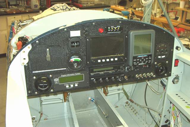
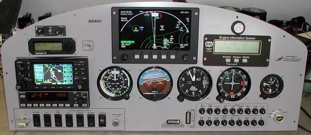
Instrument panel:
Lots of hand made holes.
Here's an equipment list:
Grand Rapids Horizon Series I EFIS and EIS
Lift Reserve Indicator (for ASI backup if the electricals fail)
Navaid wing leveler w/Smart Coupler
Icom A200 Comm radio
PS Engineering PM501 intercom
Lowrance Airmap 2000c GPS (the Airmap 1000 shown is in the rear seat now)
Garmin GTX320 transponder
Drop down LCD screen coupled to a forward looking video camera is shown here:
http://vincesrocket.com/LCD%20in%20use%202.jpg
Each one gets its own carefully milled, drilled, and filed hole. An easy days work after hours of agonizing over the layout.
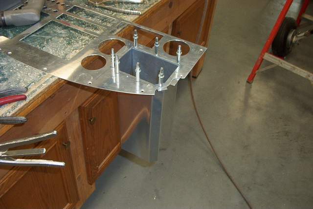 I had enough room for a chart box custom made to exactly fit a sectional chart.
This is something I could only dream about in my round gauge packed panel in my
RV-4. I love those new electronic instruments... and NO $#%$&ing
vacuum system to screw around with.
I had enough room for a chart box custom made to exactly fit a sectional chart.
This is something I could only dream about in my round gauge packed panel in my
RV-4. I love those new electronic instruments... and NO $#%$&ing
vacuum system to screw around with.
Speaking of storage space... my RV-4 had exactly one glove box in front of the stick and one baggage compartment behind the seat. My Rocket has 4 storage areas accessible from the front seat and I could add 2 more. This doesn't even count the areas around the rudder cables where you can easily stuff charts, etc.
In the back there is the usual baggage area, another baggage area behind that for lightweight stuff, and another baggage area above the rear seat back (ala Tom Martin) for purses, headsets, etc. Very cool indeed.
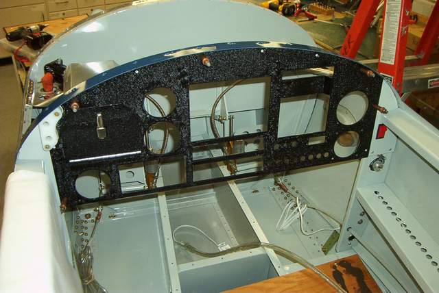 3-19-04: Here's the empty panel during a trial
fitting.
3-19-04: Here's the empty panel during a trial
fitting.
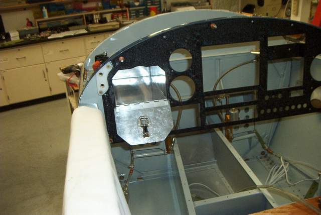 There is exactly enough room for a sectional map sized glove box.
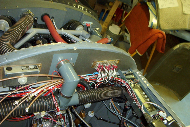
 The backside of the panel is getting crowded already, and there's no wiring
installed yet!
The backside of the panel is getting crowded already, and there's no wiring
installed yet!
 5-11-04: The Grand Rapids Technology EFIS arrived yesterday.
More on this after I connect the wires!
5-11-04: The Grand Rapids Technology EFIS arrived yesterday.
More on this after I connect the wires!
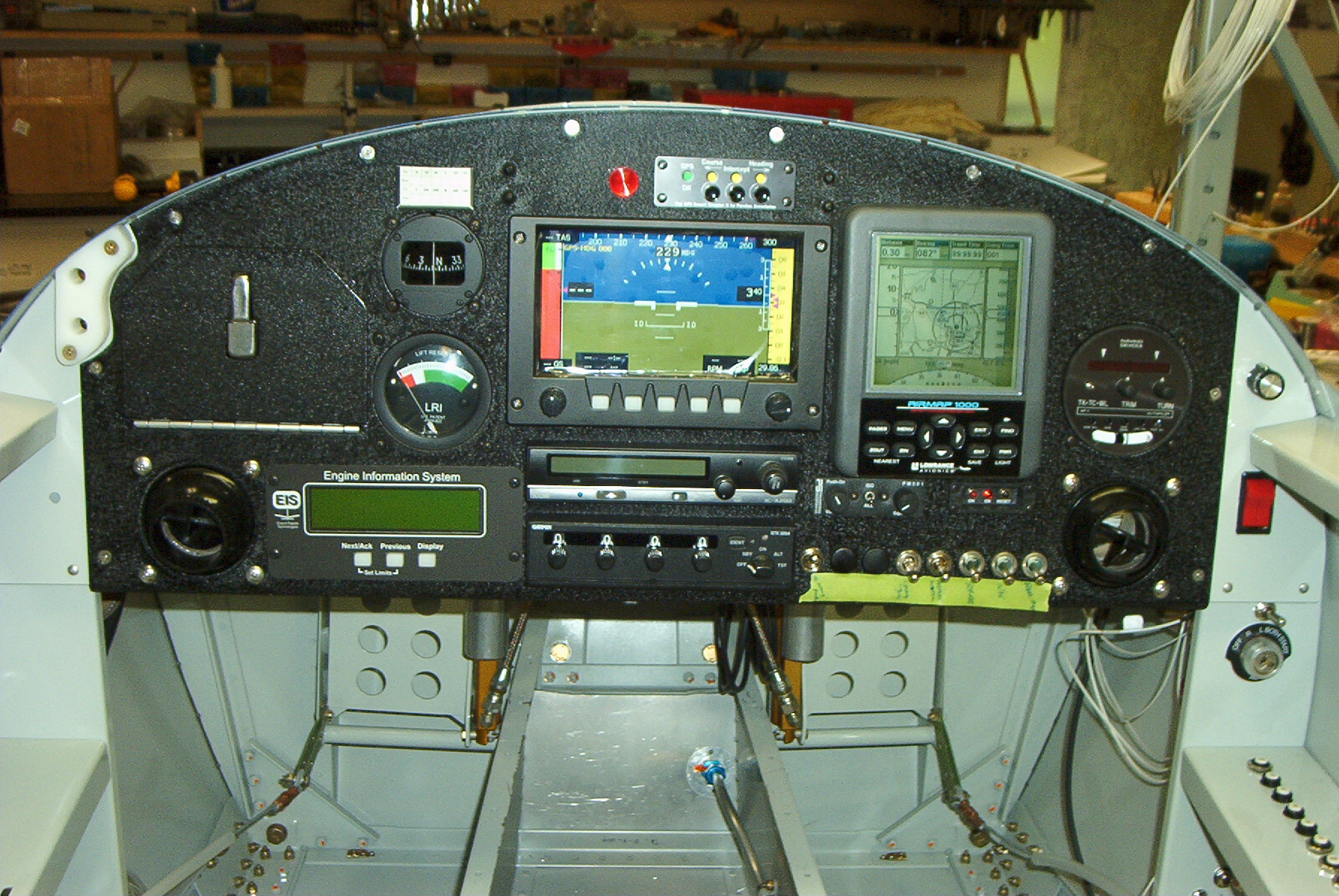
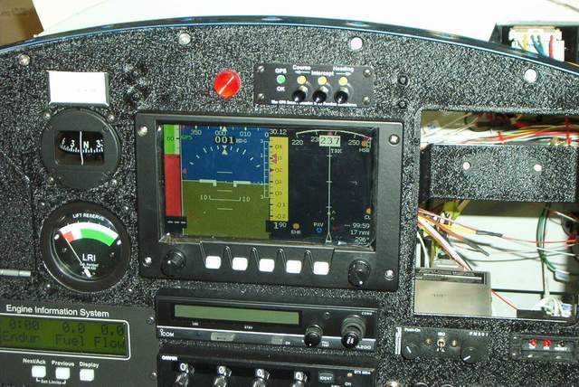
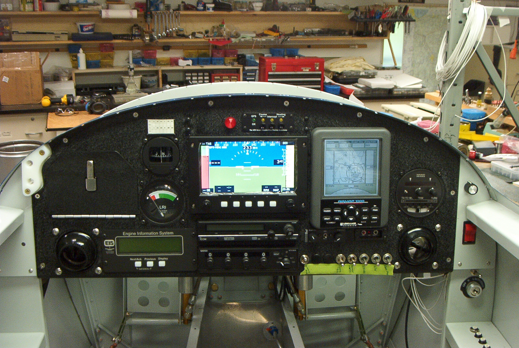 5-13-04: The Grand Rapids Technology EFIS. Photo
taken without a flash. Notice how bright the screen appears.
5-13-04: The Grand Rapids Technology EFIS. Photo
taken without a flash. Notice how bright the screen appears.
 The Grand Rapids Technology EFIS. Photo taken with a flash. Notice
that the screen is NOT washed out. If you look really closely,
you'll see that the protective plastic is still stuck to the screen in these
photos. If you peel if back, there is no glare on the screen at all.
Unfortunately, I didn't get a picture of it that way. I'll get one later.
The Grand Rapids Technology EFIS. Photo taken with a flash. Notice
that the screen is NOT washed out. If you look really closely,
you'll see that the protective plastic is still stuck to the screen in these
photos. If you peel if back, there is no glare on the screen at all.
Unfortunately, I didn't get a picture of it that way. I'll get one later.
Even under bright lights ( we stuck a light right next to the screen) it does not wash out. I haven't had it in the sun yet, but I can say without a doubt that my Dynon (that I sold) would NOT perform under the same conditions. No slam against the Dynon, but I could hardly read it under normal shop light and it was poor in the sun, IMHO.
The magnetometer is a bit different. When you hook it up and move it around, nothing appears to change on the MFD. GRT says that the magnetometer is designed to move in conjunction with the AHRS otherwise the compass readings don't immediately move. GRT said that the magnetometer is designed to detect long term trends (seconds? minutes? hours? I'm not sure). So, it seems to work just fine for now. When I can actually move the plane around, I'll verify the rest of the operation.
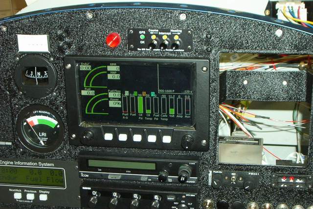 The engine monitor page, taken with a flash. I can't get over how nice and
bright the screen is.
The engine monitor page, taken with a flash. I can't get over how nice and
bright the screen is.
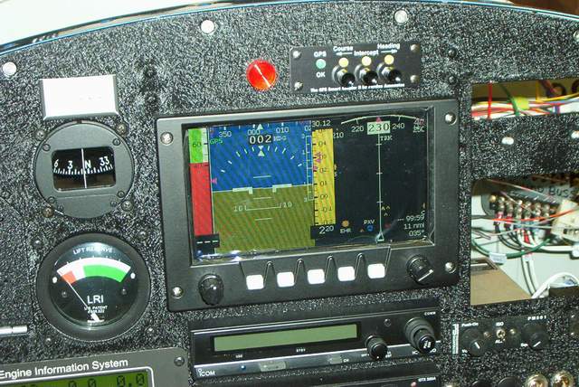
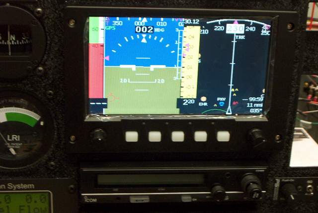 Split display, taken without a flash.

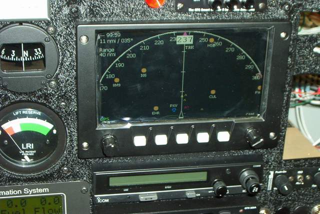
 Miscellaneous shots. The big hole in the panel is where the Lowrance 1000
GPS lives. It was outside, 50' away, so we could get a real signal to feed
to the MFD. It works great even though we had the wiring connected through
a long extension cord with multiple clip leads.
Miscellaneous shots. The big hole in the panel is where the Lowrance 1000
GPS lives. It was outside, 50' away, so we could get a real signal to feed
to the MFD. It works great even though we had the wiring connected through
a long extension cord with multiple clip leads.
 The GRT magnetometer.
10-14-04: The GRT stuff works great, but it has its own set of quirks, mostly related to setting up the interface parameters.
I had to read the GRT manual 3 times before I made it through without falling asleep.
Yesterday, I decided to turn off nearly all of the EIS warnings since the EFIS also gives a warning and I don't want to have to clear two sets of warnings. Clearing warnings off of the screens occupied a large portion of the first flight... very inconvenient. I think I've got it whittled down to where the EFIS will be doing almost all of the human interface tasks.
I did leave a few major warnings programmed into the EIS (low oil pressure, high oil temp, high CHTs) simply because if the EFIS took a crap during a flight, I'd still like to have some of the warnings to remain "automatic". Assuming that you haven't flown yet, you might consider doing the same thing to minimize first flight distractions. Believe me, on the first flight you'll be looking at the numbers so hard that you won't need any warning lights!
AND FOR GOODNESS SAKE, DO NOT HOOK UP THE AUDIBLE WARNINGS UNTIL MUCH LATER (if ever). We did that on Jim's RV-8 and it just about drove the pilot to bail out due to the distractions.
Here are the parameters that I input into the EIS and EFIS. Please read the text above so you can understand what I did more easily. I have a stock Lycoming IO-540 with Bendix fuel injection, Bendix mags, all of the GRT sensors, Van's fuel guages, and a Lowrance 1000 GPS. RocketEISSettings.xls
Electrical:
Check out the Aero Electric site: http://www.aeroelectric.com/articles.html
I ran all my wires in a 3/4 inch OD poly conduit that I bought at the hardware store for about 5.00 total. Three 10 ft pieces did the trick. Battery cables run along the inside of the two lower center longerons and through the spar section at the center break. Antennas located on the belly cables run forward in the same area. So far everything has gone through the center spar split without interfering with the controls. Hope this helps with your routing questions. Larry #001
Batteries: I found a great source for
batteries. These are late production 35AH AGM (Absorbtive
Glass Mat) batteries. They fit the rocket perfectly, weigh 25 lbs. Much better than a gel
cell. Cost was $39 each. Search the web for AGM batteries and educate yourself. You'll
like it! They had 500 in stock. I bought 4. P/N PTU135 $32.95 + $6.00
S/H
Battery Size U1
Sunn Battery Company
Jacksonville, FL
904-354-4508
Bob Gross
Wiring on N540VF:
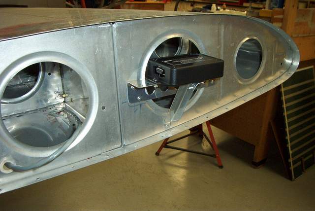
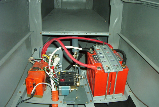
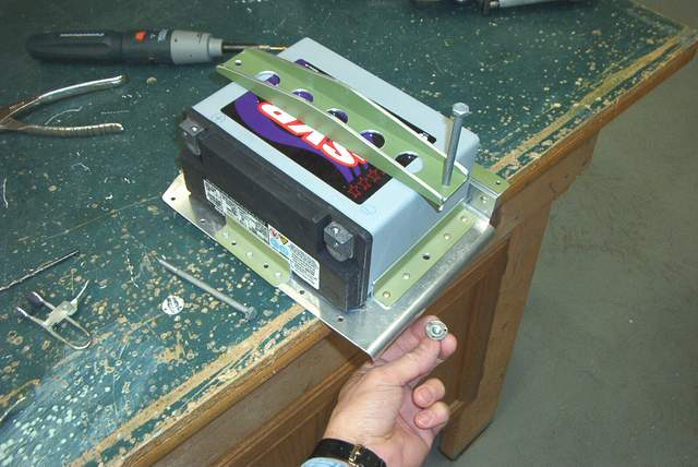 I'm using an SVR absorbed glass mat battery.
http://www.svrbatteries.com/motorcycle_line.html The literature says
that you can mount it in any orientation, even upside down. It seemed to
be nice and stable laying on its side, so that's how it's mounted.
I'm using an SVR absorbed glass mat battery.
http://www.svrbatteries.com/motorcycle_line.html The literature says
that you can mount it in any orientation, even upside down. It seemed to
be nice and stable laying on its side, so that's how it's mounted.
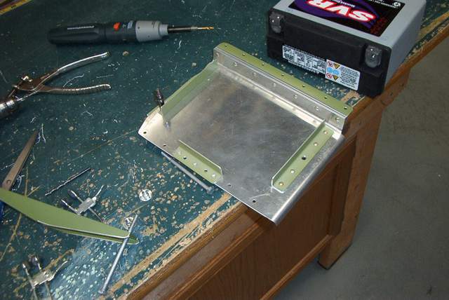
I couldn't find a AN nutplate to fit the coarse threads of the hold down bolts. However, the aviation supply aisle at Lowe's had a suitable nut in their miscellaneous hardware bins. I riveted it to the bottom of the tray. Works fine.
 I used cheap and flexible #2 welding cable behind the firewall. I
chose not to use any airframe grounds opting instead for a heavier, more
complicated, more costly 2-wire system. Why? Because in my
experience ( I do this type of stuff for a living) there are many, many problems
caused by ground problems, often related to dissimilar metal corrosion, dirt, and
vibration... exactly the environment you have in an airplane. YMMV!
I used cheap and flexible #2 welding cable behind the firewall. I
chose not to use any airframe grounds opting instead for a heavier, more
complicated, more costly 2-wire system. Why? Because in my
experience ( I do this type of stuff for a living) there are many, many problems
caused by ground problems, often related to dissimilar metal corrosion, dirt, and
vibration... exactly the environment you have in an airplane. YMMV!
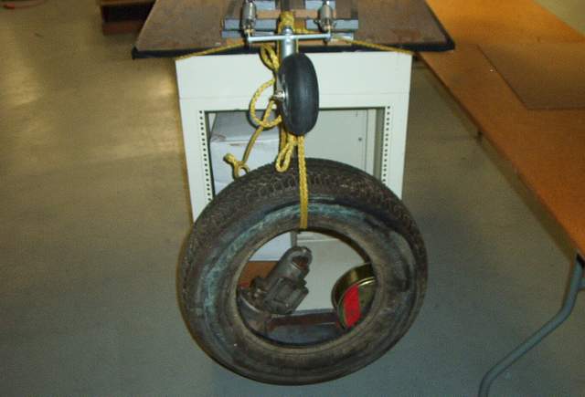 To save weight and make up for all of that heavy ground wiring that I added, I
decided to use the old 16 pound starter for something useful... holding the tail
down.
To save weight and make up for all of that heavy ground wiring that I added, I
decided to use the old 16 pound starter for something useful... holding the tail
down.
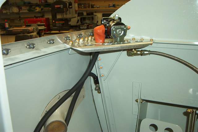
 The positive cable runs up to the starter solenoid mounted just behind the
firewall. I'll use Tefzel wire to run forward to the starter since it has
much better heat resistance.
The positive cable runs up to the starter solenoid mounted just behind the
firewall. I'll use Tefzel wire to run forward to the starter since it has
much better heat resistance.
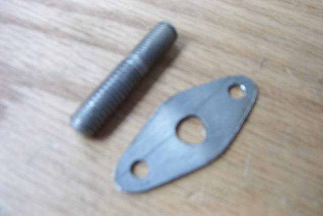
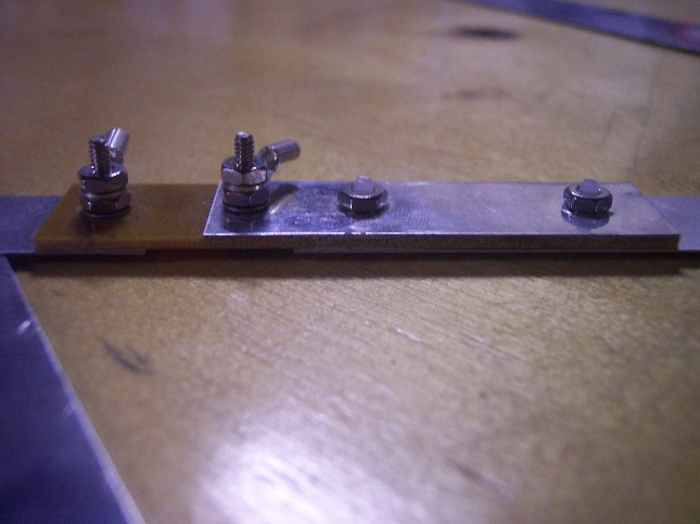
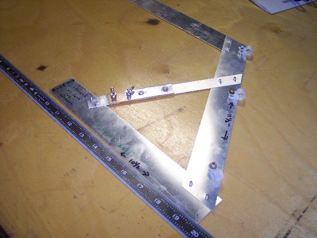
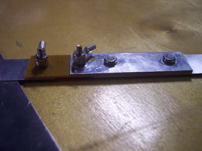
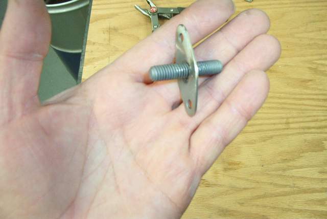 Here's the main ground lug that passes through the firewall. Many use a
convenient bolt, but I chose to put the bolt where I wanted it instead.
It's simply a bolt welded to a piece of steel.
Here's the main ground lug that passes through the firewall. Many use a
convenient bolt, but I chose to put the bolt where I wanted it instead.
It's simply a bolt welded to a piece of steel.
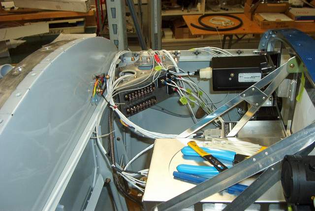
 Early wiring. Getting the juice from the battery to the breakers.
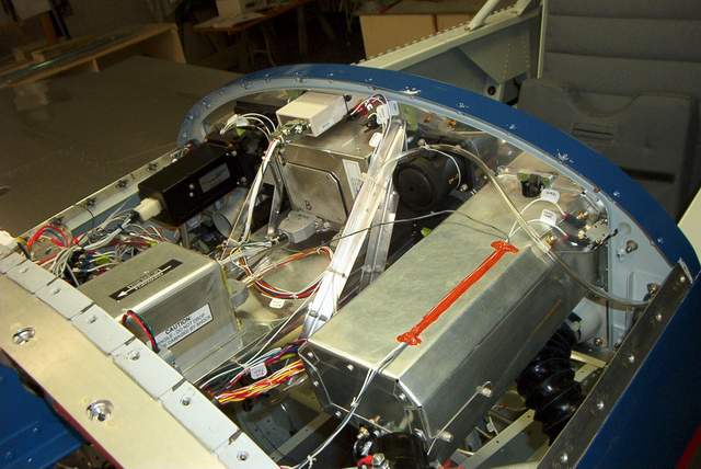
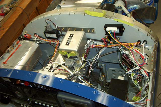
 Later on it looks like this.
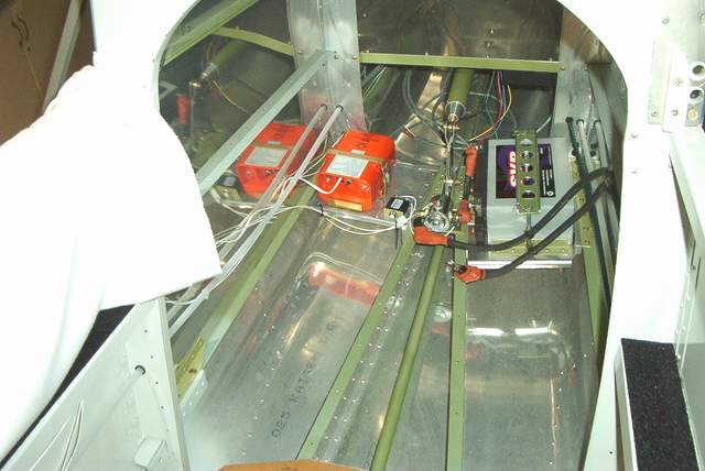
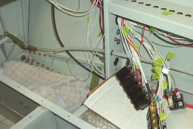
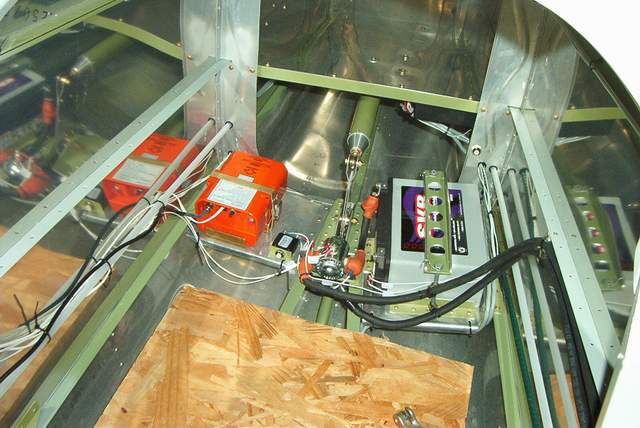 The aft wiring. You can see a lonely breaker near the ELT. It's part
of the essential buss. In the second photo the breaker on the bulkhead
above the battery is for the strobes.
The aft wiring. You can see a lonely breaker near the ELT. It's part
of the essential buss. In the second photo the breaker on the bulkhead
above the battery is for the strobes.
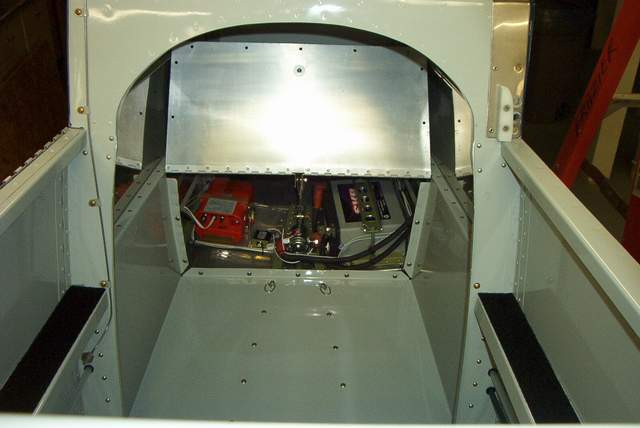 Later it looks like this.
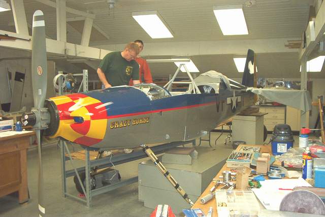
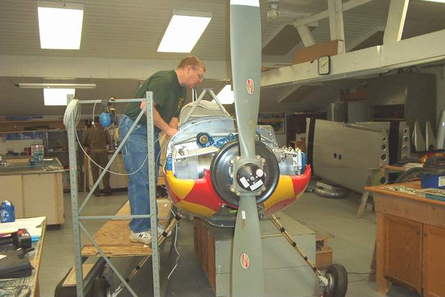
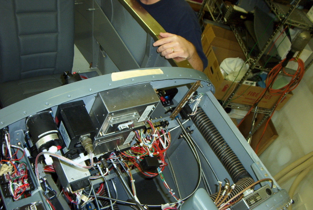
 Here you can see John Crabtree working furiously on the wiring. Meanwhile,
I am so infatuated by the recently installed prop that all I can do is stand and
drool. John was a big help on the wiring, which allowed me to concentrate
on other stuff. It's interesting that John did much of the wiring,
considering that I'm an instrument tech!!!! It certainly seems like I
should do the wiring and John should do the other stuff. Go figure!
Well, there's plenty of wiring to share anyway!
Here you can see John Crabtree working furiously on the wiring. Meanwhile,
I am so infatuated by the recently installed prop that all I can do is stand and
drool. John was a big help on the wiring, which allowed me to concentrate
on other stuff. It's interesting that John did much of the wiring,
considering that I'm an instrument tech!!!! It certainly seems like I
should do the wiring and John should do the other stuff. Go figure!
Well, there's plenty of wiring to share anyway!
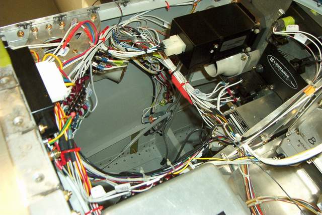
 The ground buss behind the instrument panel. A little more wiring to do it
this way, but hopefully no ground problems... ever!
The ground buss behind the instrument panel. A little more wiring to do it
this way, but hopefully no ground problems... ever!
 Now you see it, now you don't. I made a pair of cockpit lights for the
pilot. They are made from automotive type LED units. The units can
be made to provide red, green, or a combination of red and green (sorta
yellowish) light. I wired mine through a rotary switch so I can have any
of those choices. The lights are cleverly mounted on a fully swiveling
gadget that I made from junk BNC connectors. The BNC connectors don't
provide any power, just a mechanical swivel. Cheap, effective, and I can
point the lights at anything in the front cockpit.
Now you see it, now you don't. I made a pair of cockpit lights for the
pilot. They are made from automotive type LED units. The units can
be made to provide red, green, or a combination of red and green (sorta
yellowish) light. I wired mine through a rotary switch so I can have any
of those choices. The lights are cleverly mounted on a fully swiveling
gadget that I made from junk BNC connectors. The BNC connectors don't
provide any power, just a mechanical swivel. Cheap, effective, and I can
point the lights at anything in the front cockpit.
 The front and rear headset jacks. The other jacks are for headset power
(noise canceling), stereo input, cigarette lighter type power jacks, heated
seat switches (yes, heated seats. they are very nice.) and cockpit lights.
All of the loose wires for all of these devices are intended to lay on the
floor, mostly out of the way for ease of entrance and egress.
The front and rear headset jacks. The other jacks are for headset power
(noise canceling), stereo input, cigarette lighter type power jacks, heated
seat switches (yes, heated seats. they are very nice.) and cockpit lights.
All of the loose wires for all of these devices are intended to lay on the
floor, mostly out of the way for ease of entrance and egress.
 This little beast is a 70 amp truck fuse called a PAL fuse. It protects
the alternator feed line. It is mounted under the glove box where I can
fairly easily get to it for maintenance if needed.
This little beast is a 70 amp truck fuse called a PAL fuse. It protects
the alternator feed line. It is mounted under the glove box where I can
fairly easily get to it for maintenance if needed.

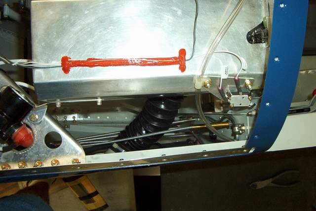 9-10-04: The completed panel. The big silver box with the RTV stuck
to the top to hold the wires down is the glove box. The funny row of bolts
on the back of the firewall is to hold the oil cooler supports. The
rest... well, you can email me if you really need to know.
9-10-04: The completed panel. The big silver box with the RTV stuck
to the top to hold the wires down is the glove box. The funny row of bolts
on the back of the firewall is to hold the oil cooler supports. The
rest... well, you can email me if you really need to know.
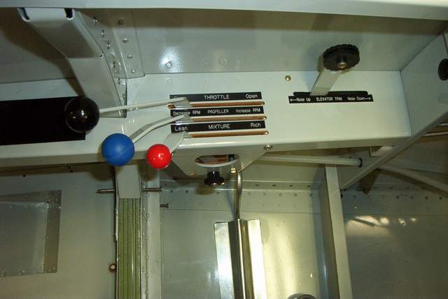
 Throttle quadrant and elevator trim stuff. The throttle levers are bent
(cut actually) in a banana shape so that I can easily reach them with my arm on
the arm rest. Lazy? You bet!
Throttle quadrant and elevator trim stuff. The throttle levers are bent
(cut actually) in a banana shape so that I can easily reach them with my arm on
the arm rest. Lazy? You bet!
The elevator trim replaces a futile attempt to use a vernier cable that had much too much play in it. You can see the threaded rod that connects the lever to the much too short RV-4 trim cable. If you look closely, you can also see the structure that had to be added to support the trim lever. It had to be shoehorned in behind the throttle quadrant, but it really wasn't too difficult.
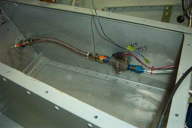 Fuel flow sensor. I've already had a couple guys tell me that I'll need a
pulse dampener. I'm using the Airflow Performance pump and they were using
a Facet pump so I'm gonna wait and see.
Fuel flow sensor. I've already had a couple guys tell me that I'll need a
pulse dampener. I'm using the Airflow Performance pump and they were using
a Facet pump so I'm gonna wait and see.
Instrument panel placards
Everyone asks me why these airplanes cost so much. Here's an example:
 I could have used cheap labels from a Brother label maker, but I opted to get
nice, engraved placards from the local trophy shop. They're nice,
but for $130 they should be!!!! No offense to the trophy shop, but I
just don't see $130 here.
I could have used cheap labels from a Brother label maker, but I opted to get
nice, engraved placards from the local trophy shop. They're nice,
but for $130 they should be!!!! No offense to the trophy shop, but I
just don't see $130 here.
I saw a Cessna 180 panel yesterday that had the labels silkscreened on it. Looked great. Cost less than I spent for the shitty placards. DOH! Of course, you have to be able to take the parts out of the plane to get them to the silkscreener.
Static system:
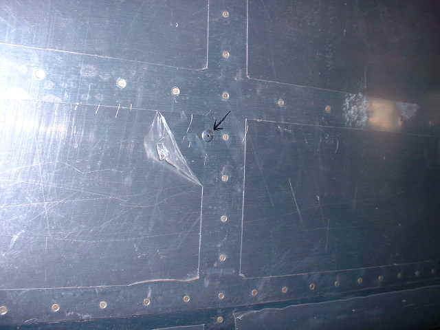
I tried an experiment with this Rocket and two static port locations. One on the aft fuselage, and the other on the pitot head. I have tried both and found no difference. The pitot head with the static port is a little on the large side, it looks out of proportion with the airplane, so on the F1 that I am building now the static port is on the aft fuselage just behind the #9 bulkhead. Tom Martin *end of comment*
Since I commented that the pitot-static test on my F-1 indicated little or no error in altitude or airspeed, I have been asked to pass on the location of my static ports.
I installed two ports---one on each side about midway vertically on the fuselage. I don't recall the bulkhead number, but just in front of the bulkhead located at the rear of the luggage compartment is where the "T" for the ports is located. The ports themselves are just in front (cockpit side) of that bulkhead. Again, that bulkhead is approximately 18'' forward of the leading edge of the tail horizontal stabilizer. Another way to pinpoint the bulkhead that I am talking about is that it is the one located at the aft end of the canopy slide mounted on the top side of the fuselage. Hope this helps. Jim Cash *end of comment*
Static system leak testing is easy and requires no tools. Get a helper who won't laugh at you too much and stick them in the cockpit with a stopwatch. Tape over one of the static ports. Stick your lips around the other static port and suck on it until your helper tells you that the altimeter reads 1000 feet or whatever altitude you deem necessary to obtain a nice difference from where you started. Now stick your tongue over the static hole to plug it and have your helper tell you when one minute has elapsed. If everything goes according to plan you'll easily detect any leaks and your helper will have at least 5 photos of you giving your airplane a hickey. Ewwwwwwwww! Vince Frazier *end of comment*
Airspeed indicator calibration:
miles/knots inches
17.4/20 0.20
26/30
0.44
34.8/40 0.79
43.5/50 1.23
50/57.5 1.63
69.6/80 3.16
70/80
3.20
86.9/100 4.94
100/115 6.56
104.3/120 7.13
110/126.5 7.95
120/138 9.48
130/149.5 11.14
130/150 11.18
150/172.5 14.87
173.9/200 20.04
200/230 26.71
217.4/250 31.63
First column is the airspeed in knots/MPH, second column is inches of water. Very simple accurate manometer made with 4 feet if 1/4 inch clear tubing from the hardware store and a yard stick and a wire tie. Wire tie the tubing onto the yardstick in the form of a long, skinny "u" shape, connect one end to the pitot tube and dribble water in the other end of the "u" to calibrate AS indicator in your airplane. Leaks indicate static or pitot connection leaks somewhere in your system, or AS indicator problems. Don't allow water to enter the pitot tube. The meniscus or "water level" or air-to-water lines indicate the pressure differences as applied to the water column in the poly tubing. The length of differences between the two lines is what you are measuring (as indicated in the second column in the above table)
Water manometers: To get all the little bubbles out all you need to do is boil the water for a few minutes prior to use. Boiling will drive out the dissolved gases that will otherwise form those zillion little bubbles in your manometer. This is a common lab practice.
Of course you still have to watch for the bigger bubbles that you might form in your manometer by mechanical action.
Manometer: a device for measuring WHAT!? Sorry, a little pun there based on that somewhat misleading name. ;-) Vince Frazier *end of comment*
Aircraft Spruce will make up an airspeed indicator for the F-1. They charge $90 extra for custom markings, but its worth it. I had mine lined as follows:
White line (flaps)-------55 MPH to 110
Green line----------------62 to 225
yellow---------------------225 to 275
redline @-----------------275
Total cost was $352 including shipping. Jim Cash, #10,Blackjack *end of comment*
Alternators:
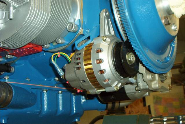
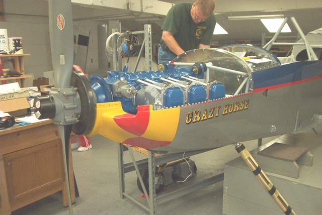
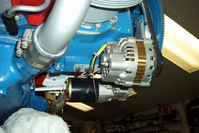 Here is the Mark Landoll alternator that is described below. It is what I
chose to use on my plane. It is modified for external regulation. It
fits up against the engine nicely, practically touching the flywheel.
I use a Goodyear 15361 belt. If I understand Goodyear's numbering system
correctly, the belt is 15/32" wide and 36.1" long. Vince
Here is the Mark Landoll alternator that is described below. It is what I
chose to use on my plane. It is modified for external regulation. It
fits up against the engine nicely, practically touching the flywheel.
I use a Goodyear 15361 belt. If I understand Goodyear's numbering system
correctly, the belt is 15/32" wide and 36.1" long. VinceA fellow in my EAA chapter was one of the engineers that designed the first internally-regulated alternator for GM. One of the other guys in our chapter owns an alternator shop, and jumped in the discussion. Based on these and other conversations here's what I've figured out: 1. The reason why they changed to internally reguated is because for every wire in a car the manufacturers figure it cost them a dollar to put it in. 2. Internally regulated alternators have a thermistor in the regulator circuit, to vary the output voltage with alternator temperature. Cold batteries take more juice to charge. 3. Because the regulator/alternator is designed and tested as a system, it is more reliable as a system. 4. One reason why the aviation folks have not liked internally regulated alternators is because some alternators are designed to be connected to the battery at all times (as opposed to airplanes where the battery is disconnected after shut-down), and can self-destruct if disconnected.
Another reason is some alternators will not shut themselves down if the field voltage is removed. On some cars the EFI computer delays switching the alternator online until the bus voltages stabilizes after the car starts, designed to be 'once turned on, always turned on.' There was no need to shut down the alternator, so that capability was never built in, unless you stop it and remove the key. Those are the alternators we don't want; I believe that is the type of alternator that Van's sells. 5. I have been flying with a Denso alternator that is controlled thru the field wire...in other words I can shut the thing off in-flight by switching off the field connection. If it wouldn't respond to that I could easily pull the 40a breaker in the panel, and I see no reason why an airplane needs current limiters if you're running #2 wire. No need for any external contactors or OV modules since it has OV protection built in. Part # is Denso 18504-1620, used in the Toyota Camry 1994+.
I believe this is similar to the Suzuki Samurai alternator. Supposedly it is the same alternator as the B&C without the guts removed. Its the same thing that Niagara airparts sells new for $225. The Niagara people told me the only return they've had was from one that looked like it had been dropped. You can pick one up at Auto Zone for $150 and have a lifetime warranty. This alternator has no reported problems like wanting to fry itself after being disconnected from the battery while running, will shut down via the field wire, and have been very reliable in my experience with them.
I installed one after going thru two externally-regulated alternators in 200 hours, haven't had a bit of trouble since. If you believe in the KISS principle, and spend money on gas rather than overhyped, overpriced airplane parts which add additional unwarranted complexity to your airplane, I think using the Denso internally regulated alternator is the way to go. Worrying about overvoltage is like worrying about getting struck by lightning. < Regards Bob
What alternator are you and Jim using? I�m pulling my hair out to find a suitable externally regulated unit. Vince
From: Bob
Japundza
Sent: Tuesday, February 17, 2004 1:24 PM
To: Frazier, Vincent A
Subject: RE alternator
Forget the external regulator. That�s old school. I looked at a schematic 2-3 years ago of the Japanese internal regulator and it has OV protection built into it. Mine and Jim�s alternators are internally regulated. 87 Suzuki Samurai. Jim�s is rebuilt, mine is brand new bought from Niagara air parts. I�ve been flying with one in the -6 with no problems at all. Regards, Bob
Bob,
I saw some info that the Suzuki alternator is the basis for the ones that Lycoming gets from Pelican. Maybe you told me that� I can�t remember.
I found 2 or three websites that had some great alternator info on them. The Autozone site had the weights listed for shipping purposes, which was very nice. The Suzuki 55 amp alt. weighs 7.7#. Nearly all other alternators of 60 or more amps weighed 12# give or take a pound.
What I learned from other sites is that there are very few alternators that rotate CCW (viewed from the front)� if that is important??? They are all made for early 90�s Hondas and Acuras. I thought that the CCW rotation would be better in aircraft to keep everything spinning and blowing air in the proper direction. ????
I was on the Autozone site, all set to order a Suzuki alternator, which was $30 cheaper online than the in-store price. Then the phone rang. It was Mike Zeller who was singing the praises of Mark Landoll�s alternators. I was skeptical, but called Landoll anyway. Phone Mark at 405-685-0239 or 405-392-3847.
Landoll, who has been around Oshkosh for at least 20 years selling stuff out of the back of his RV, seemed to have a pretty good assortment of stuff to sell including larger pulleys (not really necessary according to him), mount brackets, external regulators, etc.
I got everything, externally regulated (at John�s insistence and my agreement), mount brackets, adjustable regulator, etc, from Mark Landoll for about $140. I couldn�t touch that price for the Suzuki alternator alone (if you include the core charge), so it was a no-brainer. He claims his Mitsubishi alternator weighs 8# and puts out 60 amps. Mike Zeller has one and claims that it is a really nice unit. It is possible that Landoll�s is one of these CCW units� I�ll let you know when it gets here.
Very few alternators have external regulation (ER) anymore. Dodge was the last to do much with ext. regulators from what I saw online. Crabtree was insistent that we have ER on ours. His argument was that you can disconnect the battery with the master switch, something that you cannot do in a car, while the engine is running. So, if you�re using an internally regulated (IR) alternator, which is self exciting, in an airplane and shut off the master switch it is possible that your alternator could do some funny things to your circuits. Possible? I suppose. Likely? Beats the #$%^ out of me! I�ll err on the safe side on this one since I really don�t want to fry $10,000 worth of inst. panel for a stinking $15 regulator.
That�s my story�. Vince
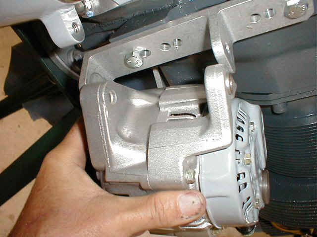
 Here's an internally regulated alternator modified for external regulation.
Other options:
Auto-Zone haz `em--Dura-last#14824 $102.99 plus $55 deposit so up hyar it came to $165.99 tax and all.Tell them to punch in#871772 14824 on the computer and it'll just jump out at 'em. Thanks Bill Asbell....Hey Bill: Is this one of 'em with that lifetime warranty too? Seems a breakdown enroute would be an easy repair -- availability almost anywhere!
Did you happen to get the wiring plug to fit the thing too? I always had to go to the boneyard to get one -- even the dealership doesn't carry 'em.
Also: while you're there, get one of those one-size-fits-all nifty chrome alternator adjustor arms (Mr. Gasket etc) if your engine didn't come with one. Trim to fit your application! Be sure to use a drilled-head bolt to attach the arm to the engine.
Drive belt: this varies with flywheel drive pulley size, but I have a 30.5" belt on my ship. Be sure to get the skinny lil' fella that fits the alt v pulley. Keep the alt as high as possible for cowl clearance -- it should almost touch the right front baffle. If you have a drive belt installed, let us know what size you found to fit please. Mark Frederick
Regarding pulley size: On the DENSO unit, a 4 1/4" pulley from GM can be easily modified to fit. This pulley comes from a 70's Chevrolet Camaro air pump and has the GM part# 14087007TAY. *end of comment*
Still struggling with this alternator thing. I ordered the 35 amp unit from Vans for $165. The parts arrived and had already been installed and were covered with corrosion so I sent them back. These 1978 Honda Civic alternators have quite a bad reputation for not lasting more than a couple of hundred hours. They are cheap $21 at the auto store, but seems like too much trouble changing alternators every year. BTW, they need and external regulator $40.
I spoke with the alternator guy at vans about this stuff. He told me to do as he had, and get a 60 amp unit from a 1989 Camry. I bought one for $99 and it came with a lifetime guarantee. It was a the same size as the Honda, but heavier and built better. It had an internal regulator set to 14.8 V, and the test sheet showed it belted out 83 amps!
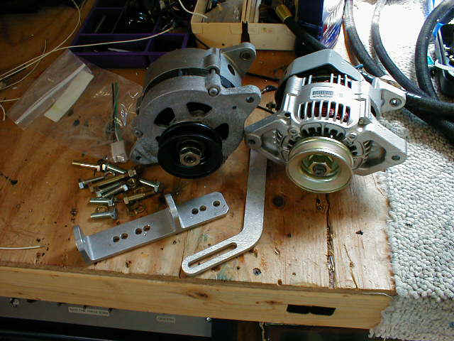
Still not being happy, I did some more research and came up with a 1989 Suzuki Samurai alternator (Nippon Denso) for $109. Now this thing is a little jewel (see pic). It is tiny, light weight and belts out an impressive 55 amps. Internally regulated to 14.6 V. Only problem is it won't fit the Vans bracket (see pic 2). I will be using this style alternator. Any of you guys know of the different part number that has a different mounting ears cast into the alternator? I saw a picture of one with a single large lug rather than the two small lugs you see in the picture.
Both of the latter units are designed for high speed ops and do not need to have a pulley change according to the guy at Vans. Thanks Bob Gross *end of comment*
Navaid
The servo for the roll control can be mounted in the front stick area on the upright floor support the goes from the spar forward to the firewall. A short 3 or 4 inch push tube is all that is needed here. It is a great location as it allows adjustments without removing floors and also requires shorter wire runs. Attached is a pic that shows the installation, it works like a charm in flight. Tom Martin *end of comment*
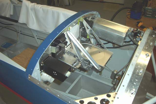
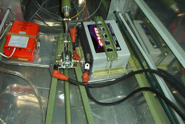
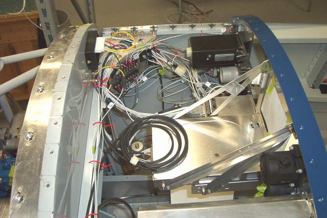
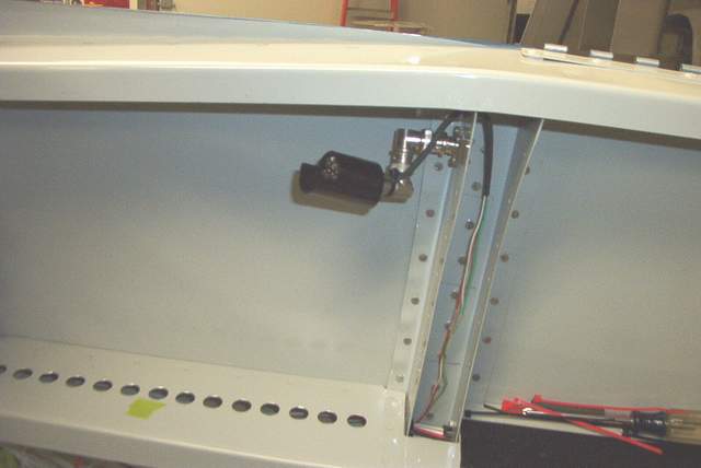
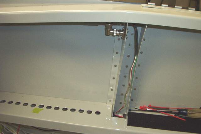
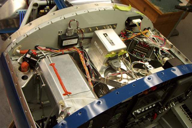
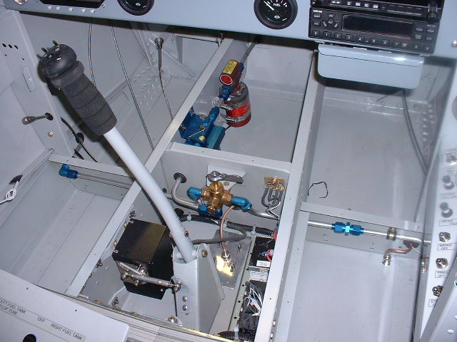
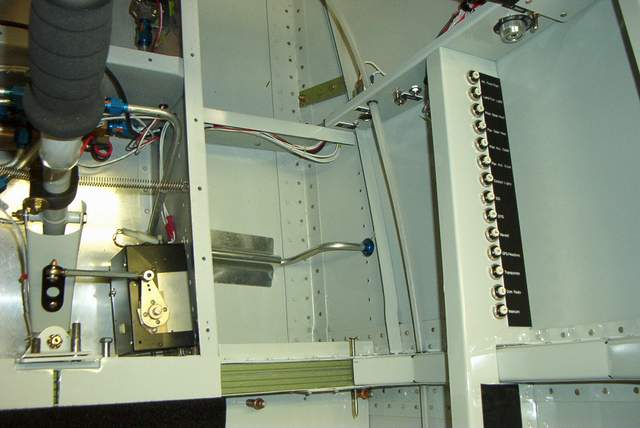
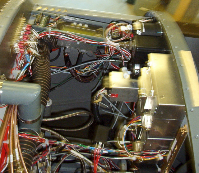
 My Navaid servo had to be packed into the center bay... because that's where I
wanted it. It is shoehorned onto the side wall in a fairly tight spot. The
servo arm doesn't move in the same plane as the control stick bracket, but I
can't see that it will make any difference... after all, you don't use the
Navaid for acro, just small navigation inputs. The rod end balls seem to
have more than enough, way more, range of motion to work just fine.
My Navaid servo had to be packed into the center bay... because that's where I
wanted it. It is shoehorned onto the side wall in a fairly tight spot. The
servo arm doesn't move in the same plane as the control stick bracket, but I
can't see that it will make any difference... after all, you don't use the
Navaid for acro, just small navigation inputs. The rod end balls seem to
have more than enough, way more, range of motion to work just fine.
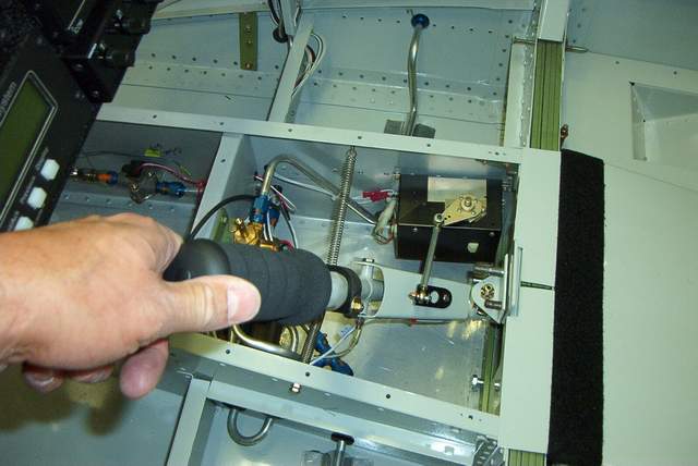
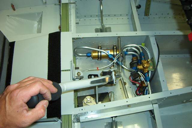
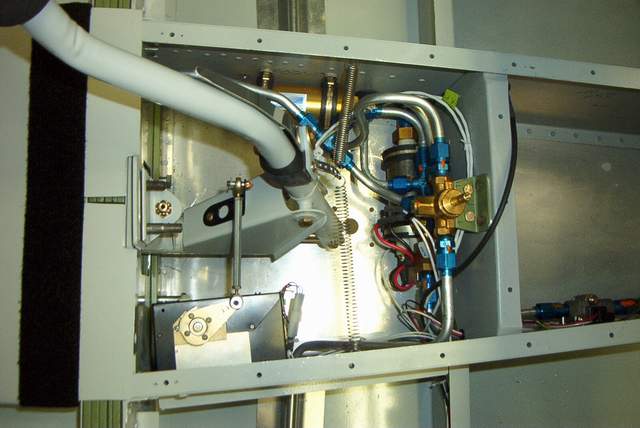
As you can see, I've got the fuel pump, fuel filter, com antenna, and Navaid stuffed in here with the control stick and fuel selector... oh yeah, and the spar bars are still accessible. I'll only need to remove one cover to access this area for maintenance.
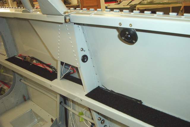
 The fuel lines pass through an inflight accessible storage compartment.
That's why they have a guard over them. That way I won't drop a heavy
object on them and damage them.
The fuel lines pass through an inflight accessible storage compartment.
That's why they have a guard over them. That way I won't drop a heavy
object on them and damage them.
Hidden antenna:
Check out Bob Archer's hidden wingtip antenna pictures that were sent to me.


 11-2005: Jim Stone's HRII electrical system
 Bob Hayner's panel
Here's my panel, made by Avionics Systems of Leesburg, VA. The center attraction is a MFD from Grand Rapids Technologies, on the left: audio panel, autopilot, Garmin 430, TX. To the right, is GRT's engine monitor, and the bottom row has the old time tools as back-up.
Charlie Cavalis wired it for me a mo ago; my hope is the plug and play part goes as advertised. It's beautiful work, but it was promised in March, came yesterday. All told, the thing cost about 30k. Bob Hayner
Return to the homepage: http://www.vincesrocket.com/
Last updated: 09/01/06
CAUTION: This web site is not a publication of, nor approved by, Harmon LLC, Team Rocket, Van's Aircraft or any other person or entity listed herein, except me. Be advised that I am a blithering idiot with neither brains nor money and my advice is not to be trusted. So there. You have been warned! Vince