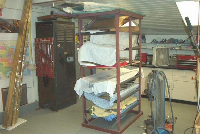
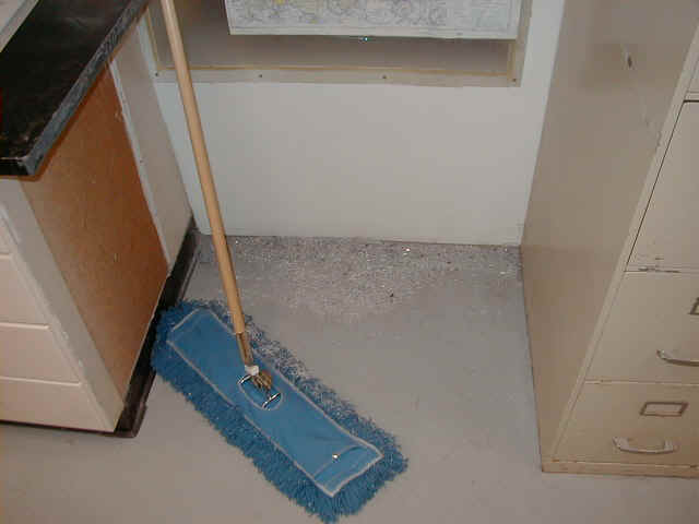
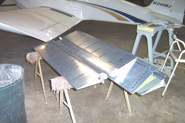
 The storage rack for the control surfaces. Made from an old swing set.
Fuselage Construction
December 12, 2001: I'm busily clearing out my shop to get started on
my fuselage. I have a steel fuselage jig that came from Jim Stone in
Louisville, KY. I can't wait to start putting parts in it.
The storage rack for the control surfaces. Made from an old swing set.

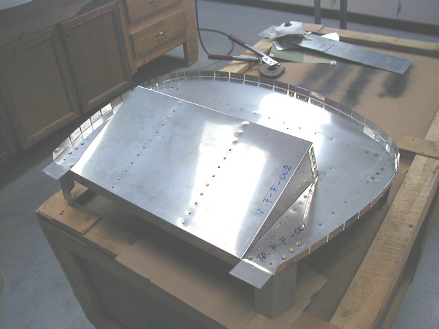
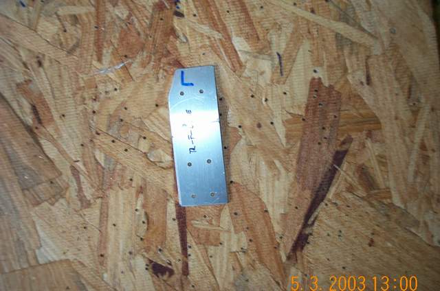
 Above: F-1 Parts
I was wishy-washy on upgrading some of my parts. I really like Mark Frederick's F-1 cowl with the removable air scoop. I also like the slightly widened lower fuselage. I finally decided to simply buy the parts I needed from Mark. Everything arrived yesterday. Wahoooooo!!!! The stuff looked great. The engine mount and axle sockets are nicely powder coated. The gear leg indexing system looks great. Some of the fuselage parts were even prepunched. Prepunched? Tell me more about this "prepunching", I do not comprehend it yet! LOL! Everything that wasn't powder coated was anodized. All the edges were smoothed, straight and perfect. I was VERY impressed. I can't wait to start the assembly. Vince Frazier *end of comment*
More details on the parts swapping: When thinking about the fuselage, I started thinking how nice it would be to incorporate some of Mark's changes. So after a little investigation, I asked Mark to sell me the parts I need. I got them last Monday. They are very nice parts. The firewall is fully assembled, the motor mount and axle sockets are powder coated, and some of the parts are pre-punched.The aluminum parts are stamped, perfectly straight, and anodized. If they fit as good as they look, I won't have any problems. (3-2002 They do fit as good as they look. Mark's stuff went together perfectly.) I got everything except the skins (the skins are the same as what I already have) from the F404 forward, up to and including the spinner. (9-10-02 Wait a minute... the boot cowl skin that Van's sells isn't big enough to fit on an F-1. Buy it from Mark. The other skins work fine.)
I sold the Harmon fuselage parts (from the main spar forward) that I won't be using to recover some of the money spent on F-1 parts.
If I were starting right now I'd probably buy Mark's slowbuild kit (if available). But since, I'm already well underway, it seemed prudent to get the majority of the upgrades... the cowl has a removable airbox to ease cowl removal, the gear is thicker and pre-indexed to the motor mount, and the firewall is wider.
I won't have the 52 gallon tanks (can't fly that long without peeing anyway), or the sliding canopy (don't want one... blocks too much visibility) or the new F-1 tail (no big deal). I call my hodge-podge an "F-1H Rocket."
Vince Frazier4/21/03 update: I put the wings on the fuselage for the first time yesterday. Due to the mix of Harmon and F-1 parts, the tank flanges are very close to the fuselage sides and required quite a bit of trimming. Everything is tight, but I think it's gonna work OK. If I were doing it again, I'd move the fuel tanks outboard AT LEAST 2 inches. *end of comment*


January 14, 2002: When laying the longerons on the jig, the front ends are bent (see "Bending the Longerons" below) to meet the firewall weldments. Mark tells me that the vertical difference between the plane of the longerons and the firewall weldments is 2.47". I had to adjust the height of my firewall (slightly higher) and the F404 (slightly lower) in the jig to make the new parts fit properly.
I jigged the F404 bulkhead, seat ribs, and rear spar attachments directly on my wings. I had to trim the top fuel tank skins to get the F404 installed as it is very tight in that area. Next I drilled a few rivet holes and clecoed it all together. Hopefully nothing will shift and my belly skins will fit perfectly, as will the spars when I insert the wings. Well, it worked last time on the RV-4!
I've got the F-1, Harmon, and Van's parts peacefully coexisting on the fuselage jig now. I've got a little more aligning to do and I'll be ready to add a few tack rivets. Considering that John's plans are very thin in this area and considering that I've got pieces from 3 different companies, things are going quite nicely. So far!
 Vince the
F-1H Rocket building maniac!
Vince the
F-1H Rocket building maniac!

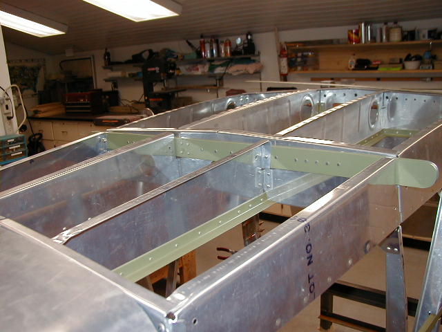
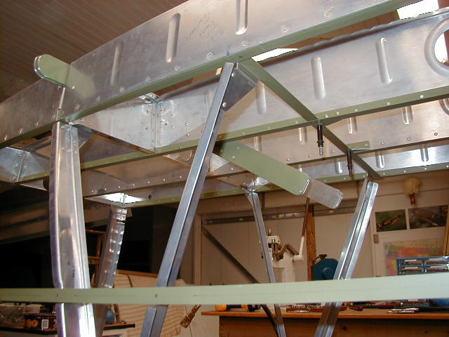
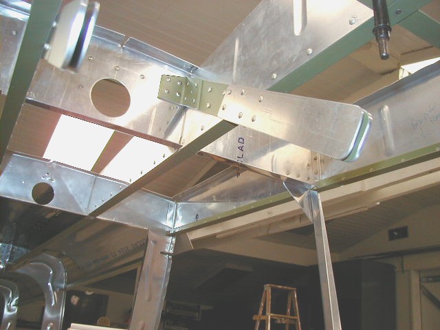


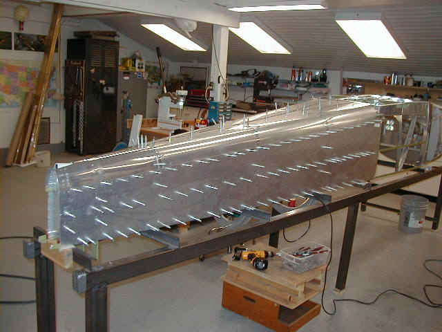
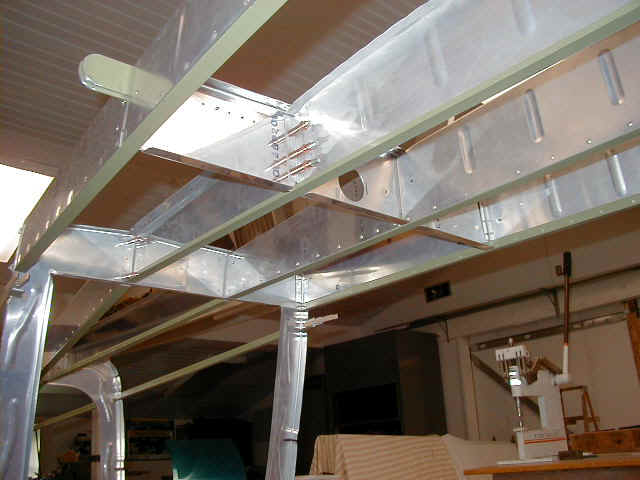
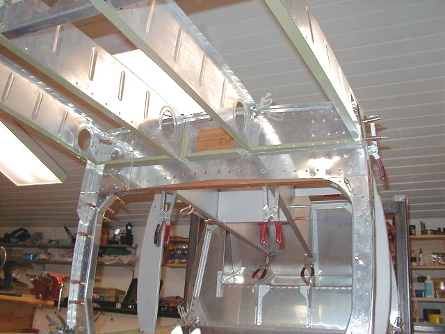
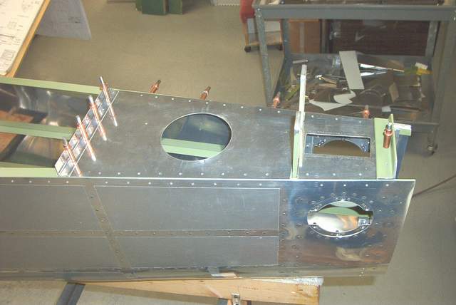
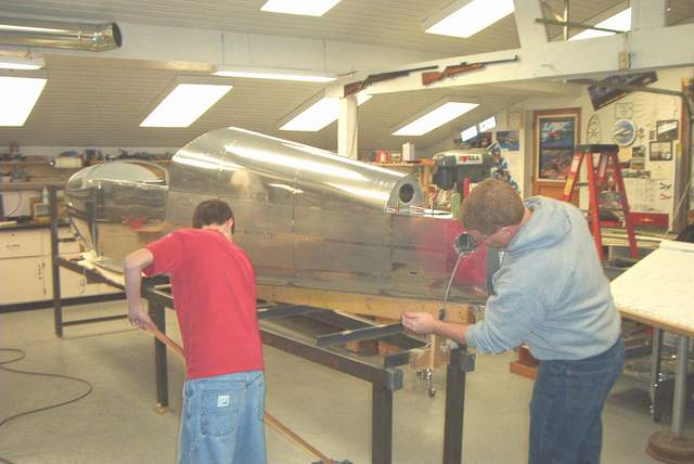
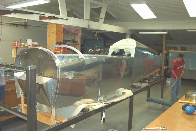
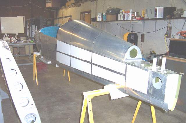
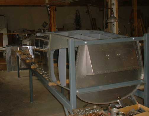
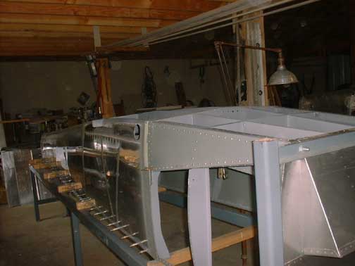
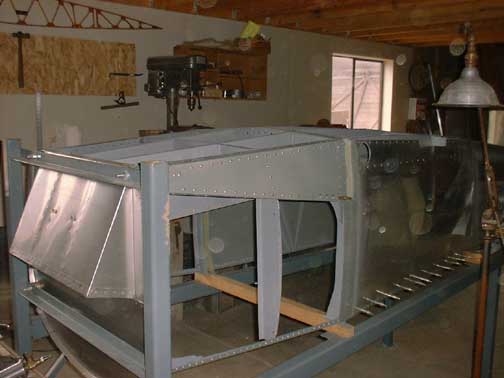
March 24, 2002: The fuselage is starting to look like a canoe. After
checking and rechecking the alignment and tacking the fuselage skeleton together, I've
started adding the skins. Wooooohooo! Well, it wasn't exactly that easy since
there's quite a bit of layout work and part making. Those pre-punched kit builders
don't know how good they have it! That last picture is a hold down clamp made
from scrap... simple and cheap.


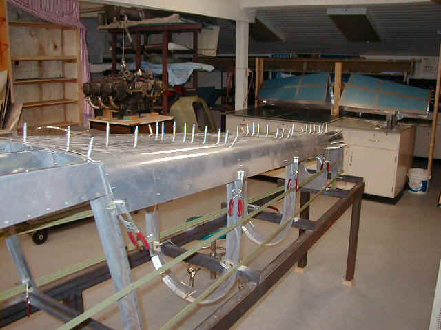
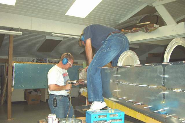
Easter weekend 2002: Not only did I get to go flying, gorge myself on Easter dinners, and be thankful to God... I made great progress on the fuselage! John Crabtree (RV-6 builder and superb Rocket helper) and I had the entire fuselage skinned in no time. My son, Blake, even took time out from his Nintendo playing to stop in and help me drill the belly skin splice strips. That last photo is evidence of the work done... look at that pile of drill shavings.
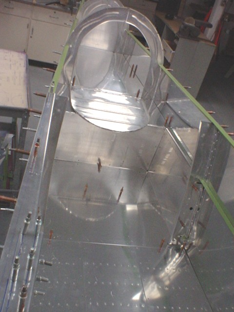
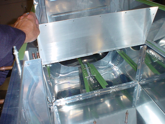
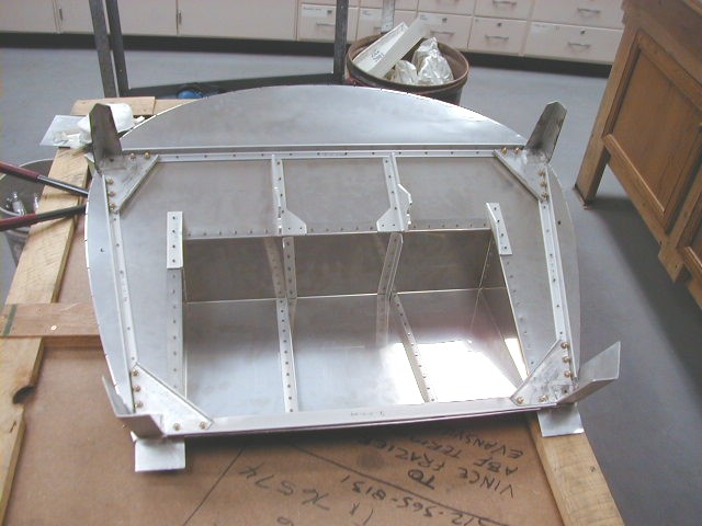
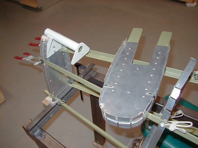
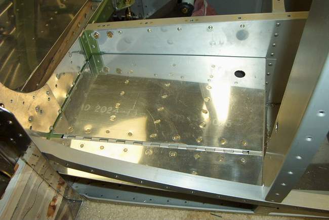
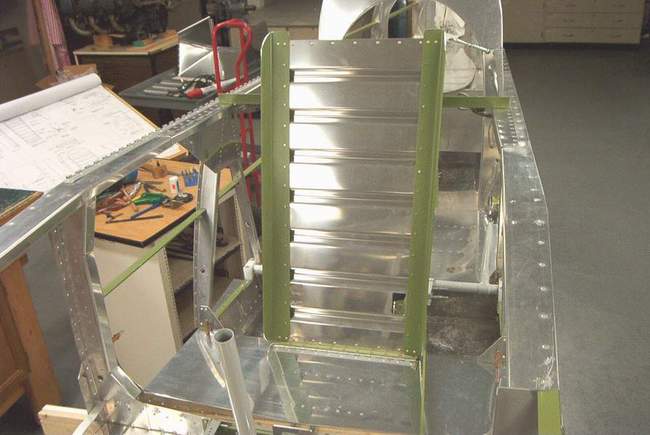
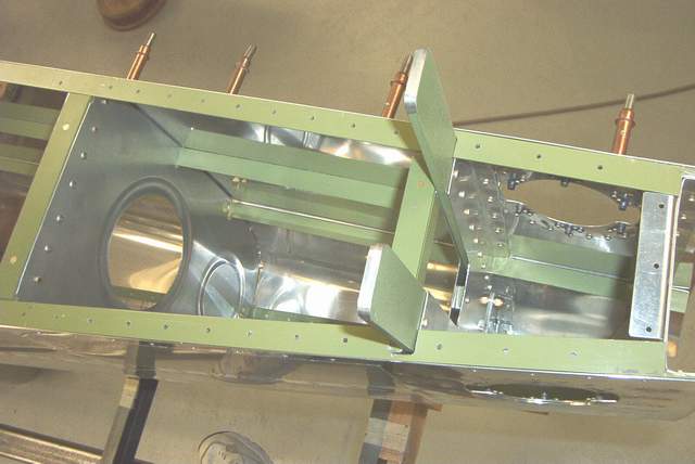
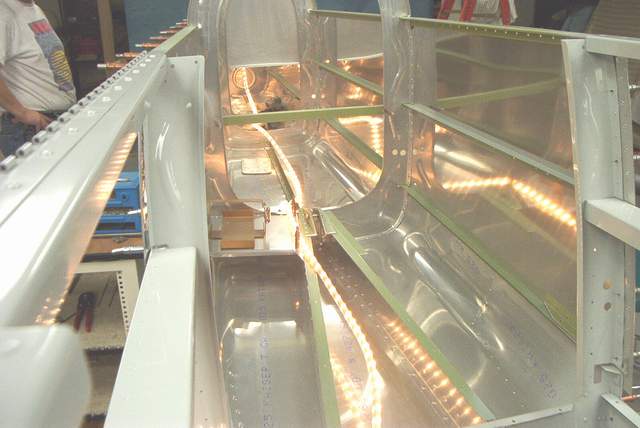
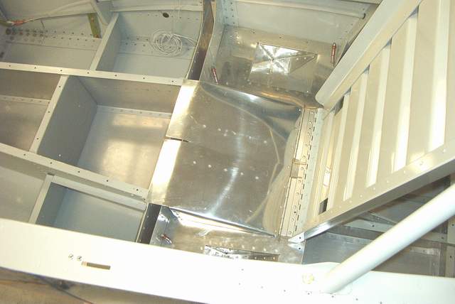
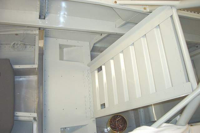
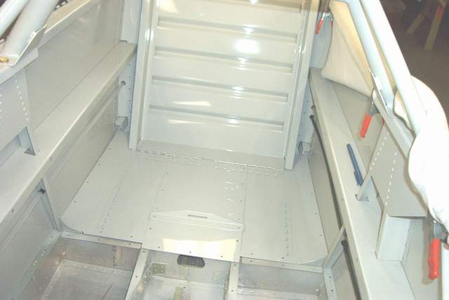
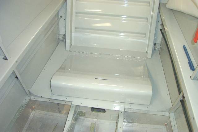
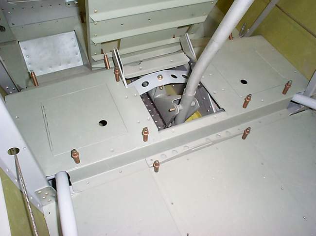
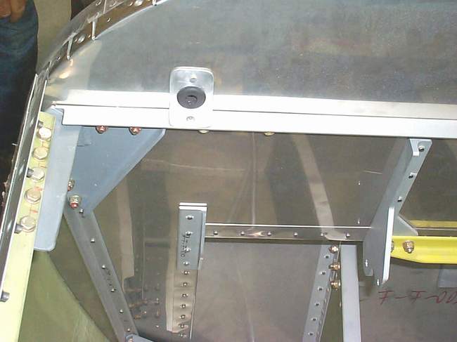
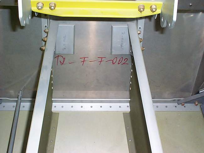
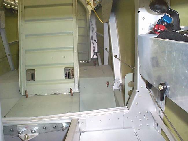
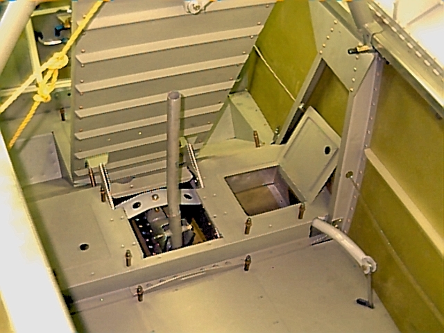
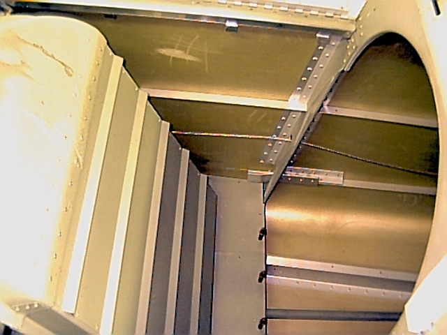
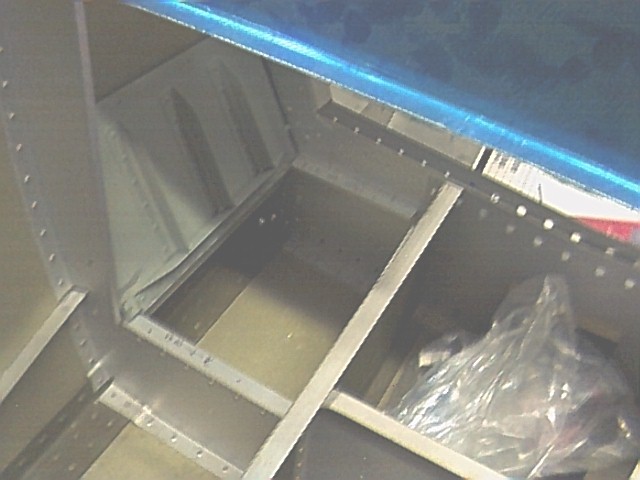
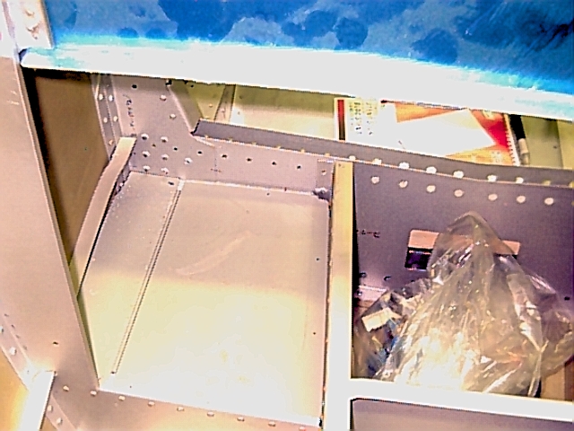
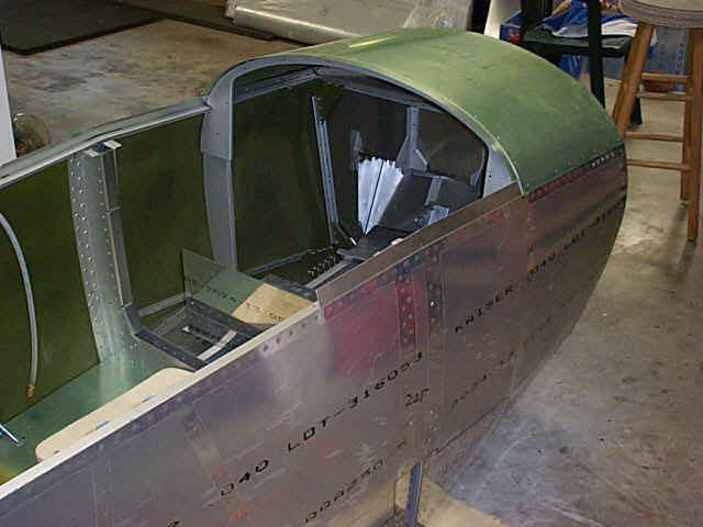
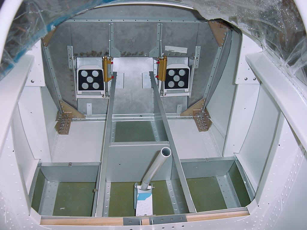
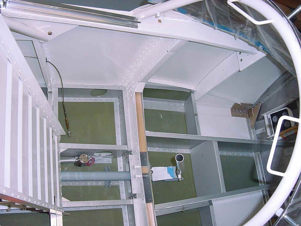
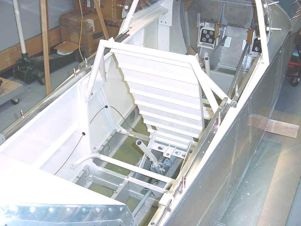
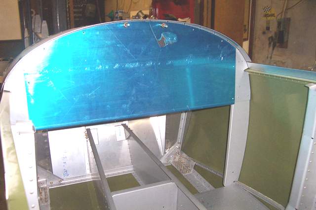
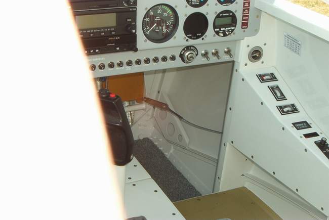
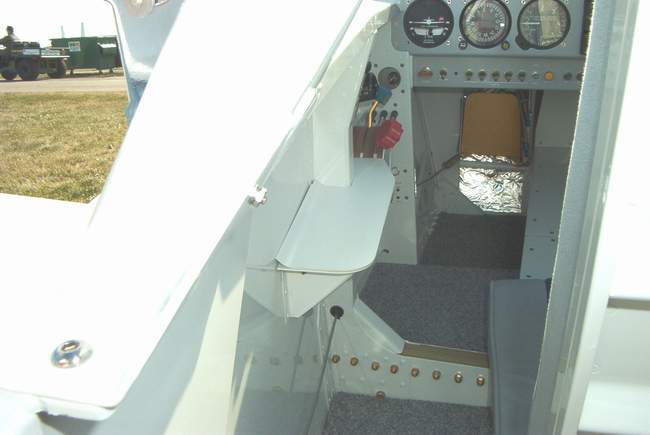
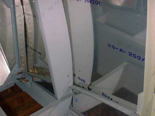
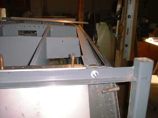
I finally found time to try out the new digital camera. Progress has been good lately and I finally feel that I've passed the QB point with my project... only 2+ years into it. That should give valuable insight to those who are trying to decide whether a quickbuild kit or a slowbuild kit is right for them. The first 2 pics, above, show the baggage compartment area. I was a bit dismayed to see how much the battery compartment encroached into the baggage area. I added the optional baggage area behind bulkhead #8 due to the small size of the main baggage area. It will be OK for lightweight stuff like sleeping bags. My F-1H will have a flop over canopy and I have decided to go with the battle proven A-frame type rollbar like I had in my RV-4.
7-16-2002: I'm ready to head to Oshkosh and spend a few bucks on airplane gadgets and tools. I plan on picking up an ELT while I'm there. Maybe a few other goodies too. I'm holding off on engine and flight instruments until I can figure out who has the best electronics. I plan to avoid putting any "steam" gauges in this time. We'll see.
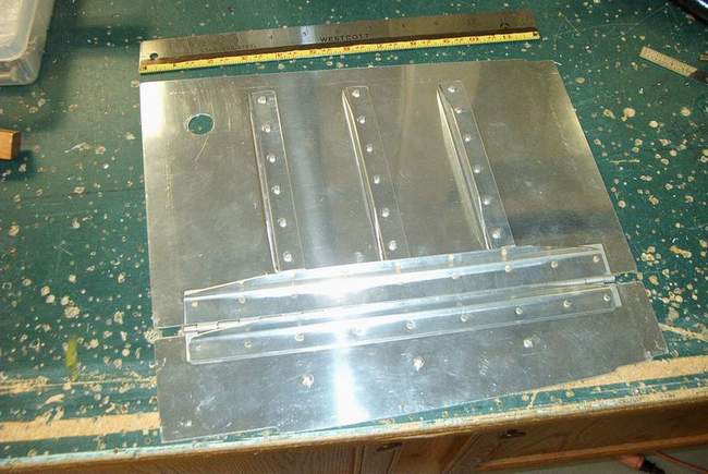
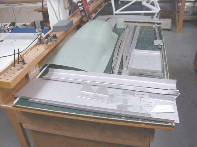
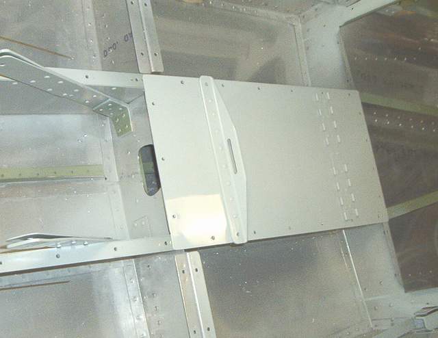
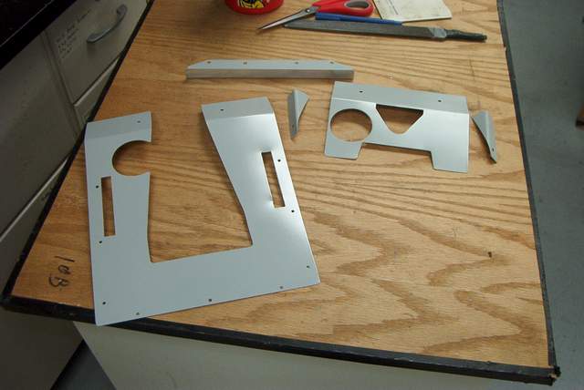
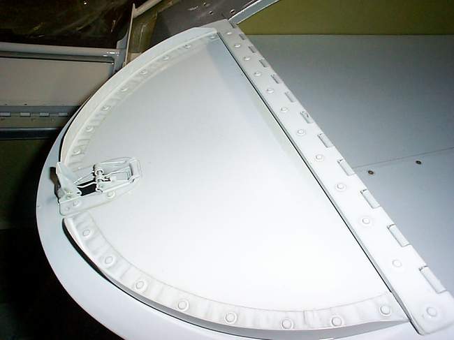
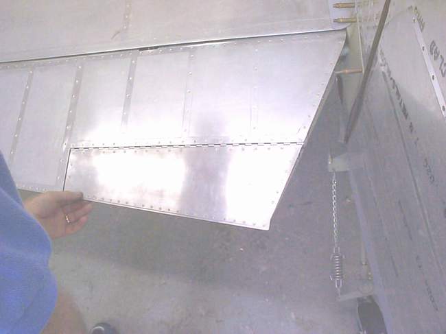
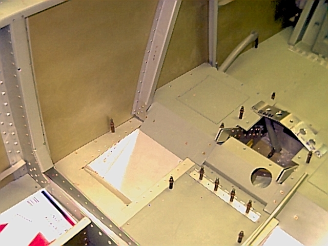
 I had these front floorboard parts finished... until I went to Tom Martin's
fly-in and decided that I had to modify mine. Under the front floorboard
area is a convenient place to store things, but how to make this area into a
storage compartment is up to you.
I had these front floorboard parts finished... until I went to Tom Martin's
fly-in and decided that I had to modify mine. Under the front floorboard
area is a convenient place to store things, but how to make this area into a
storage compartment is up to you.
I couldn't bear the thought of starting over, so I cut my floorboards in two and cobbled in a piece of hinge. So what if the rivets aren't in perfect alignment anymore? I drilled a hole to stick my finger through to facilitate opening. I added a spring latch (strip of aluminum) to make sure nothing can fly out while inverted. Tom's didn't have those. You can see it in the last picture above.
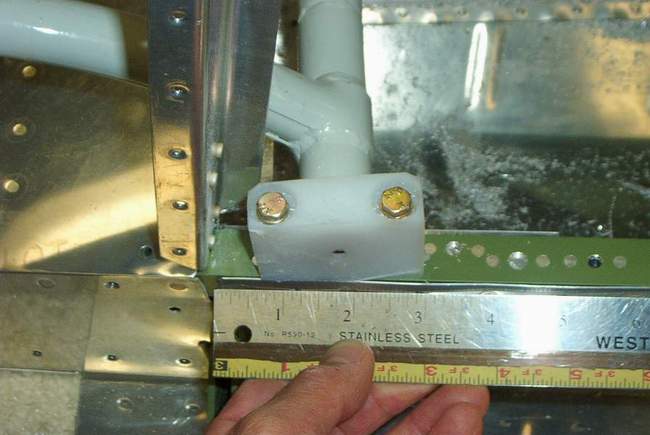
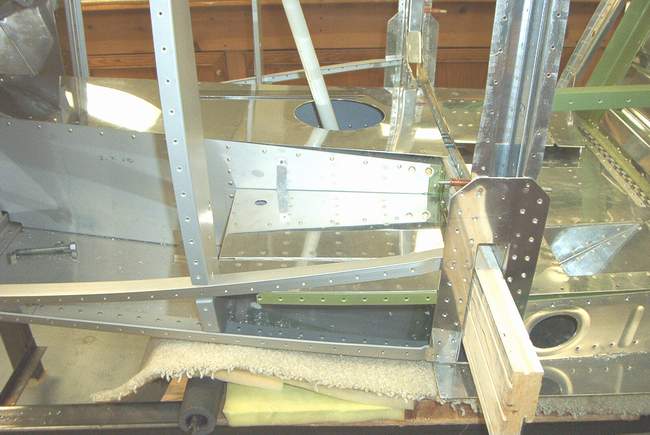
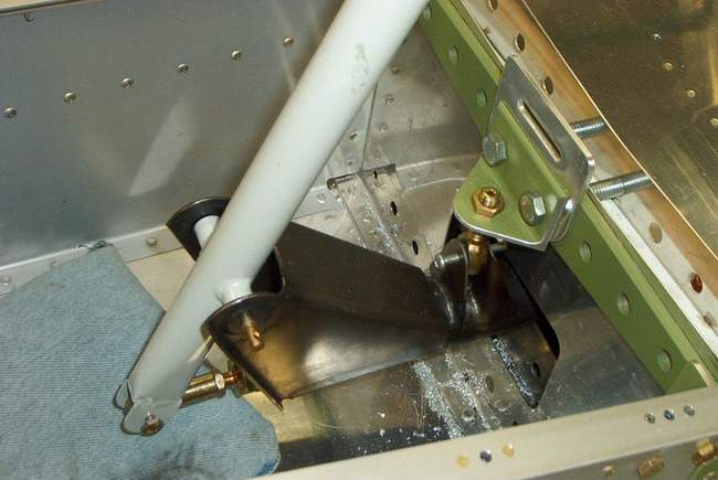
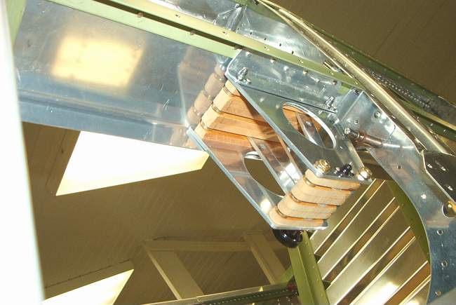
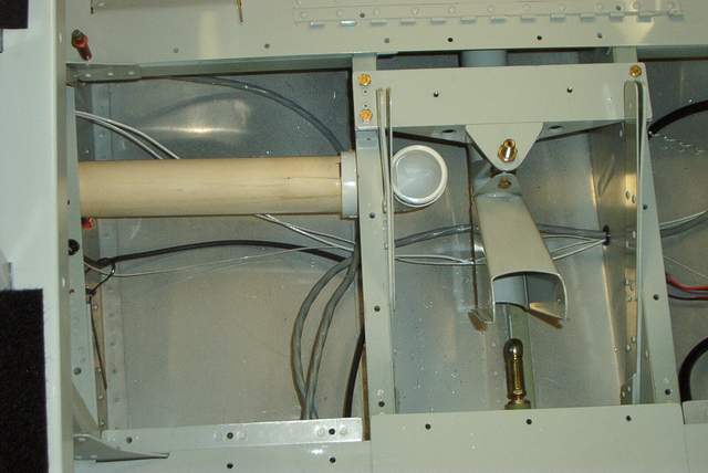
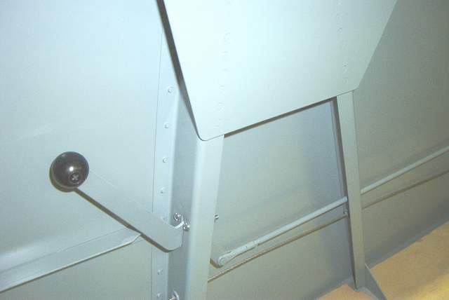
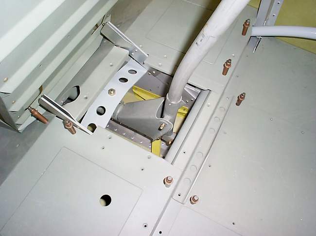
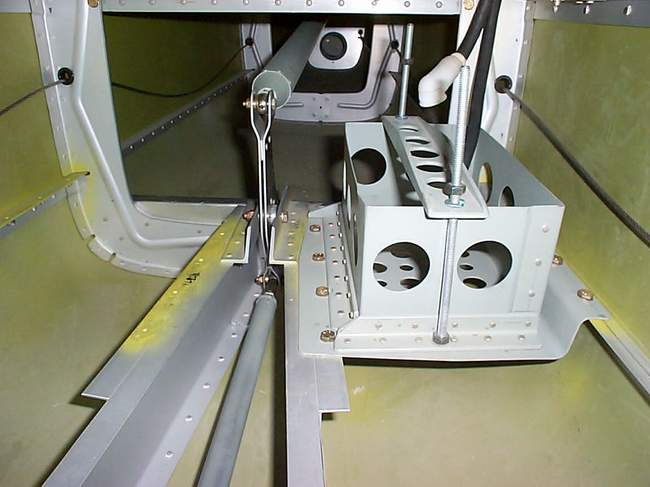
The flap mechanism gave me fits. My brain was on vacation while mounting the flap torque tube shown in the first photo above. First I mounted it per the RV-4 dimensions, thinking "How could the dimensions change, the flap hasn't moved?" Duh, brain lapse. The torque tube interfered with the control stick which did change dimensions. $%^*&!
Then I noticed that I had written down a dimension for this when I visited Mark Frederick last year. So I moved the torque tube to match his dimension. Duh, brain lapse #2. The torque tube still interfered with the control stick... just barely. $%^*&!
Then, mercifully, my brain finally kicked in and I remeasured everything and put the bloody thing were it didn't hit anything. It just goes to show that even experienced know-it-alls screw up too. This was definitely one of my biggest (that I know of) goof ups so far. Just ignore those extra holes... the doubler underneath the longeron will take care of them.
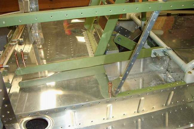
The seat is made from leftover Harmon 450 longeron parts. By using these instead of the 3/4" angle specified, the seat is about 1 1/2" wider. That's a good thing. The longeron parts are also "opened up" a bit, i.e. not a 90 degree angle. This worked out great because it allows the flap lever to be a straight piece instead of the twisted piece of crap that is on most RV-4's. I am very pleased with this area as it should work great and is cheap and lightweight.
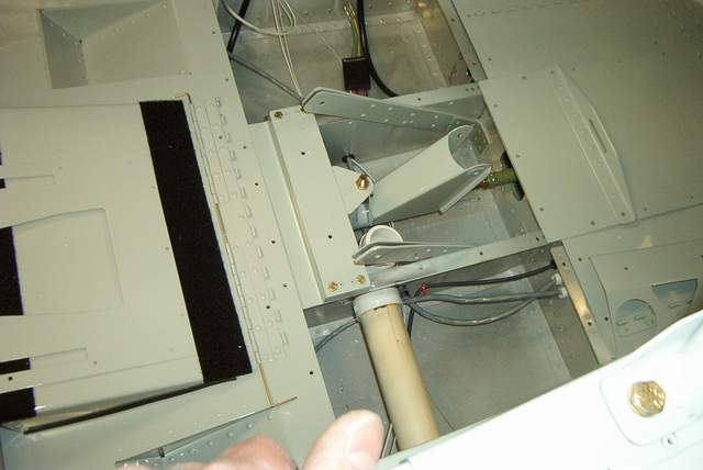
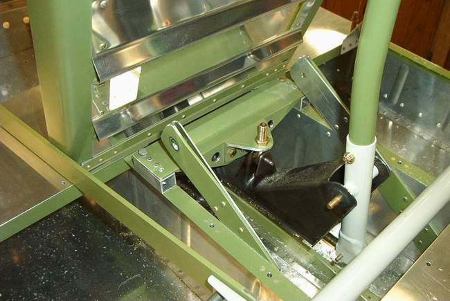 I was gonna make one of Mark's fancy one-piece control stick support hangars.
But since I had these parts on hand already I used them instead. I decided
to change the angle that the rod end hanger goes through slightly and it works
fine. Looks a little better too and since the top of the cross tube stays
flat it should be easier to put a stick boot on it.
I was gonna make one of Mark's fancy one-piece control stick support hangars.
But since I had these parts on hand already I used them instead. I decided
to change the angle that the rod end hanger goes through slightly and it works
fine. Looks a little better too and since the top of the cross tube stays
flat it should be easier to put a stick boot on it.
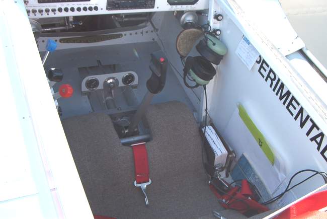
 The front stick and crotch strap attach fitting.

 I changed the rear seat belt attach fittings a bit too. You'll notice that
the angle is upside down compared to the RV-4 drawings. I reason (look
out!) that it should be a bit stronger this way since the attach bolt would push
against the extra metal above it during use.
I changed the rear seat belt attach fittings a bit too. You'll notice that
the angle is upside down compared to the RV-4 drawings. I reason (look
out!) that it should be a bit stronger this way since the attach bolt would push
against the extra metal above it during use.
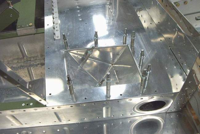
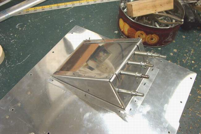
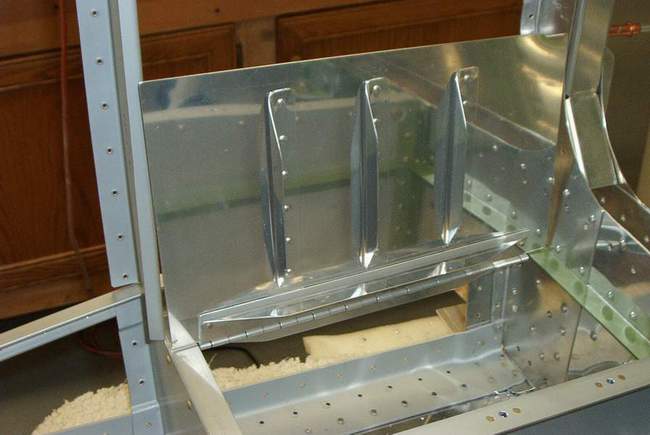
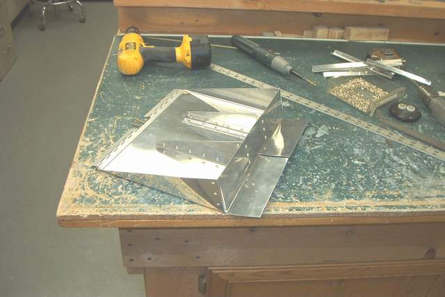
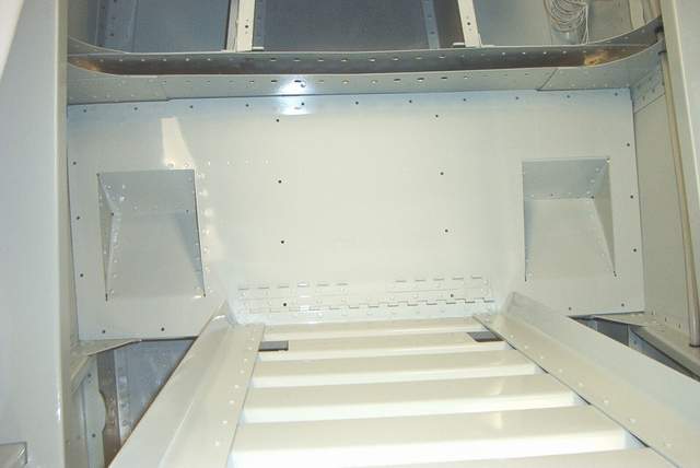
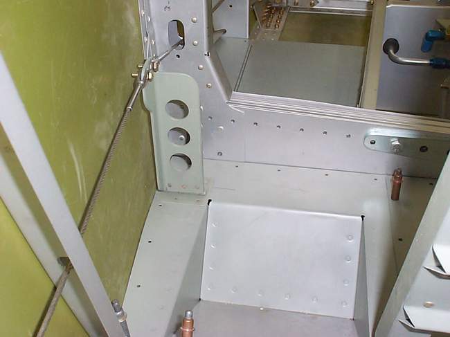
 The foot wells were fun since I didn't have any plans to cheat off of. My
RV-8 buddy said I could copy his, but he's busy finishing and soon will be
flying, so I didn't want to hold him up.
The foot wells were fun since I didn't have any plans to cheat off of. My
RV-8 buddy said I could copy his, but he's busy finishing and soon will be
flying, so I didn't want to hold him up.
You have make sure that the footwells will avoid the aileron push tubes before cutting holes in the floorboard. No other big problems. I still need to finish trimming the parts and rivet them together. I'll plop my feet into them as soon as I build a back seat to sit in.
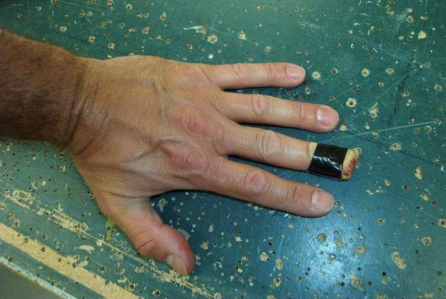 You're allowed one finger drilling accident per airplane project. I went
ahead and got mine out of the way last night while building the footwells.
I knew my finger was in line with the drill bit, but intended to stop the bit
well short of my skin. Oops. It finally stopped about 1/4" under my
fingernail. #$%^&*@!!!
You're allowed one finger drilling accident per airplane project. I went
ahead and got mine out of the way last night while building the footwells.
I knew my finger was in line with the drill bit, but intended to stop the bit
well short of my skin. Oops. It finally stopped about 1/4" under my
fingernail. #$%^&*@!!!
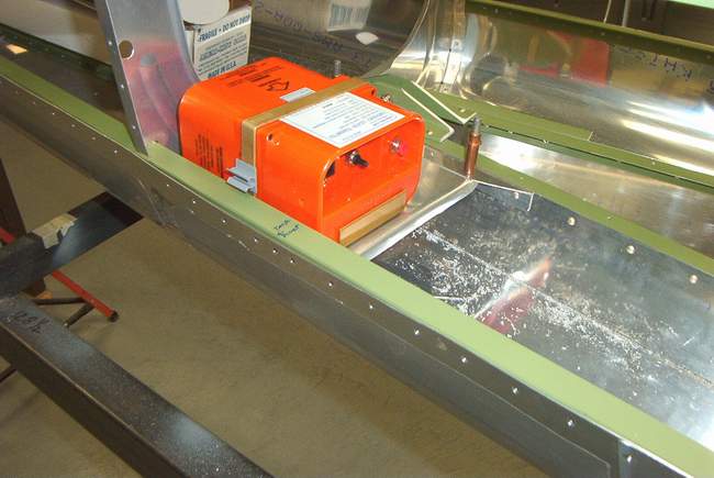
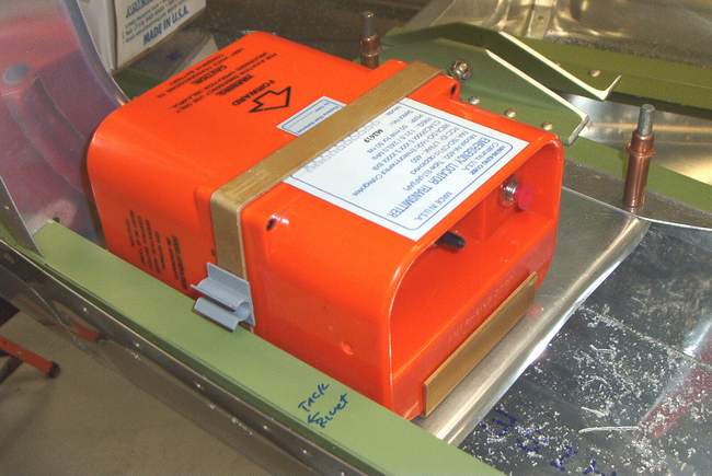
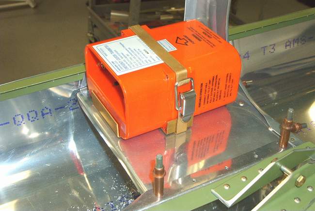 9-10-02: The ELT tray. No plans or parts were available for this
piece so I grabbed a handful of aluminum and cobbled this together.
9-10-02: The ELT tray. No plans or parts were available for this
piece so I grabbed a handful of aluminum and cobbled this together.

 10-11-02:
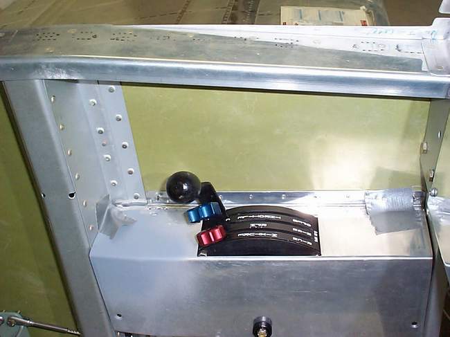
These pics show the armrests that I made. I love them. Not only do
they do arm rest duty, they also provide a convenient spot to mount the throttle
quadrant. I'll put switches on the right hand side.
10-11-02:
These pics show the armrests that I made. I love them. Not only do
they do arm rest duty, they also provide a convenient spot to mount the throttle
quadrant. I'll put switches on the right hand side.
The arm rests were part of the plan from the beginning. I simply extended the middle longeron up to the 404 bulkhead. The longeron supports the armrests and is about 13" off of the floor boards to get the proper elbow height for me.
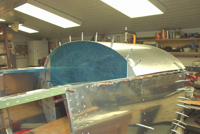
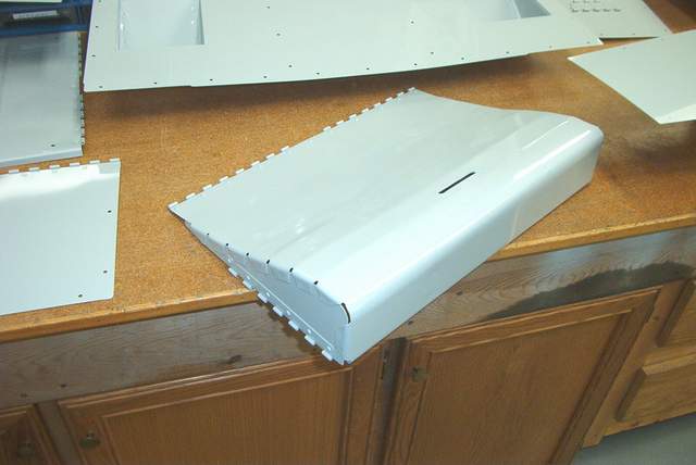
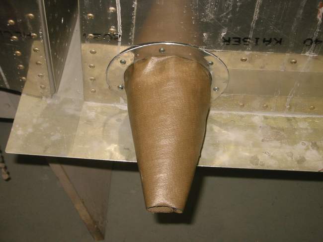
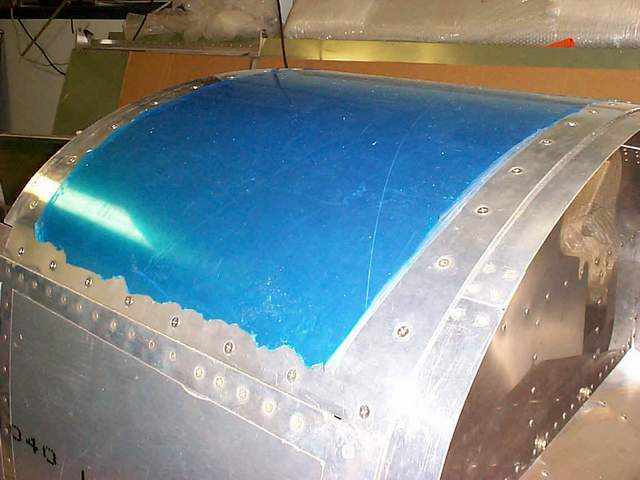
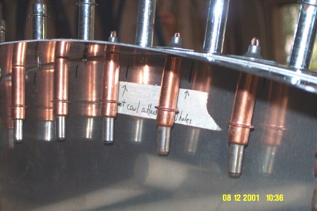
 The boot cowl was a bit of a pain since the floppy firewall was predrilled and I
had to get it to stay in position to drill up through the boot cowl.
The boot cowl flange strips run along the top longeron but are not installed in
these pics.
The boot cowl was a bit of a pain since the floppy firewall was predrilled and I
had to get it to stay in position to drill up through the boot cowl.
The boot cowl flange strips run along the top longeron but are not installed in
these pics.
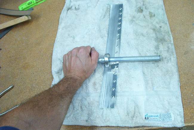
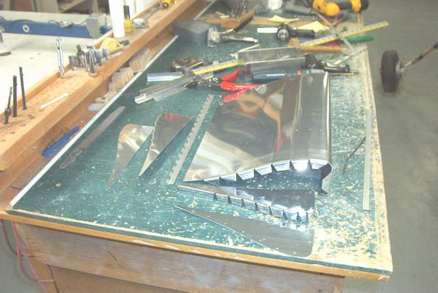
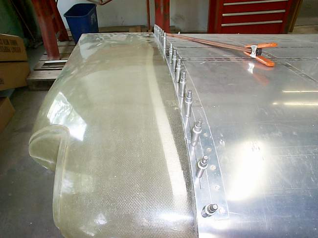
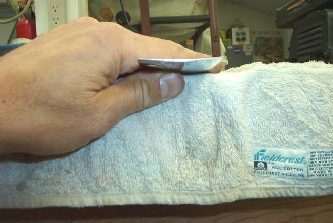 Here's how I made the boot cowl flange strips using a poor man's English wheel.
It worked great! I took an old flat sided bearing, ground the edges to a
nice round profile, stuck a steel rod through it, and... voila! The towel
under the work piece allows enough flexing that the metal stretches quite nicely
and controllably. The second photo shows the curve produced. FWIW, I
made a beautiful set of cowl panels for my C-35 Bonanza using this technique.
Those panels were compound curved and about 18" x 10". English
wheel? You don't need no stinkin' English wheel! Well, not for
simple projects anyway.
Here's how I made the boot cowl flange strips using a poor man's English wheel.
It worked great! I took an old flat sided bearing, ground the edges to a
nice round profile, stuck a steel rod through it, and... voila! The towel
under the work piece allows enough flexing that the metal stretches quite nicely
and controllably. The second photo shows the curve produced. FWIW, I
made a beautiful set of cowl panels for my C-35 Bonanza using this technique.
Those panels were compound curved and about 18" x 10". English
wheel? You don't need no stinkin' English wheel! Well, not for
simple projects anyway.
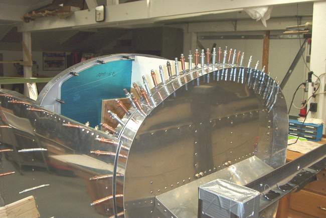
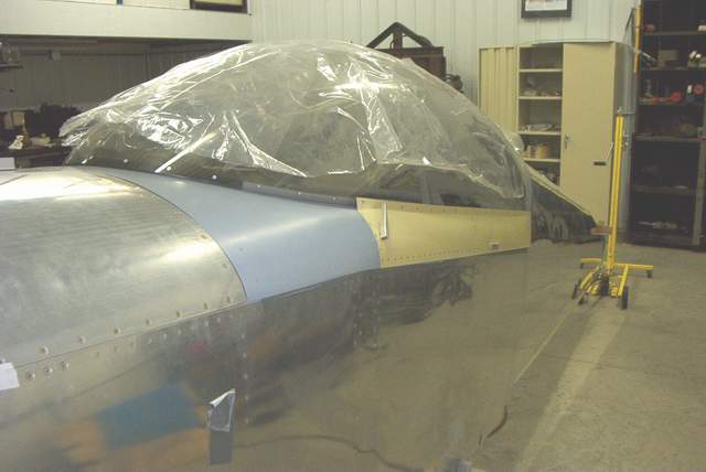
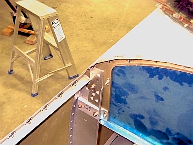
 The rear deck behind the canopy didn't fit well due to the canopy bubble change.
Fortunately this is a very easy piece to make. I used some left over side
skins from my pile of Van's parts. I plan to modify my rear seat to eliminate the warped piece of crap fiberglass seat top that
Van's sold me. The seat will be all aluminum just like my RV-4 seat. Stay
tuned on this one.
The rear deck behind the canopy didn't fit well due to the canopy bubble change.
Fortunately this is a very easy piece to make. I used some left over side
skins from my pile of Van's parts. I plan to modify my rear seat to eliminate the warped piece of crap fiberglass seat top that
Van's sold me. The seat will be all aluminum just like my RV-4 seat. Stay
tuned on this one.

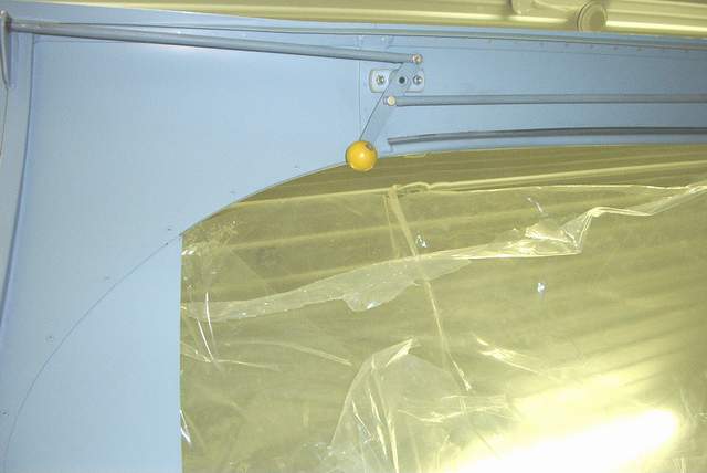
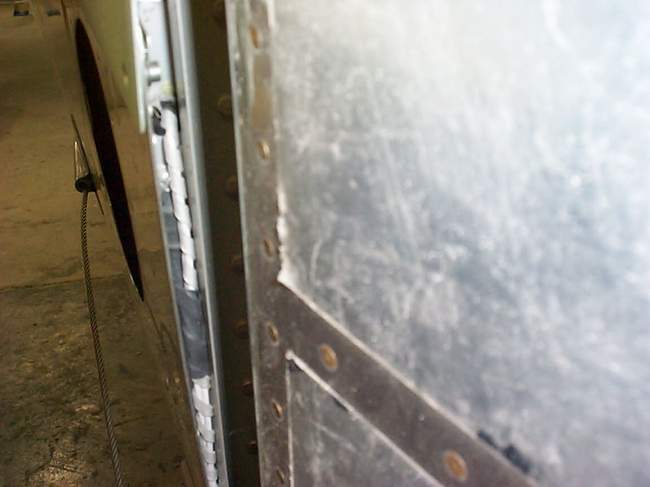
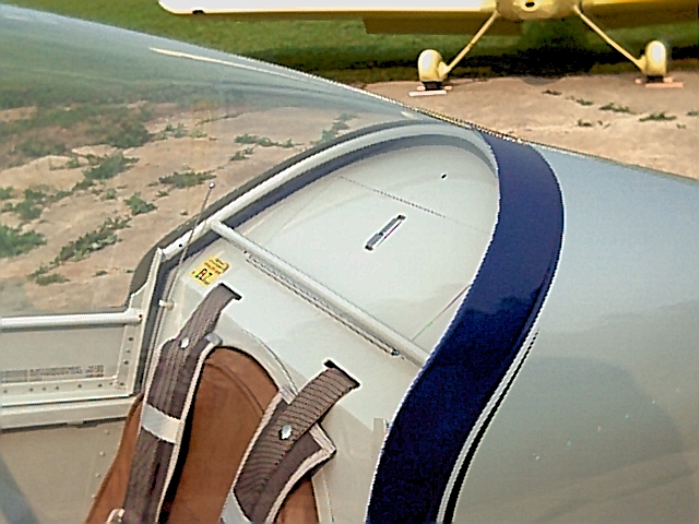
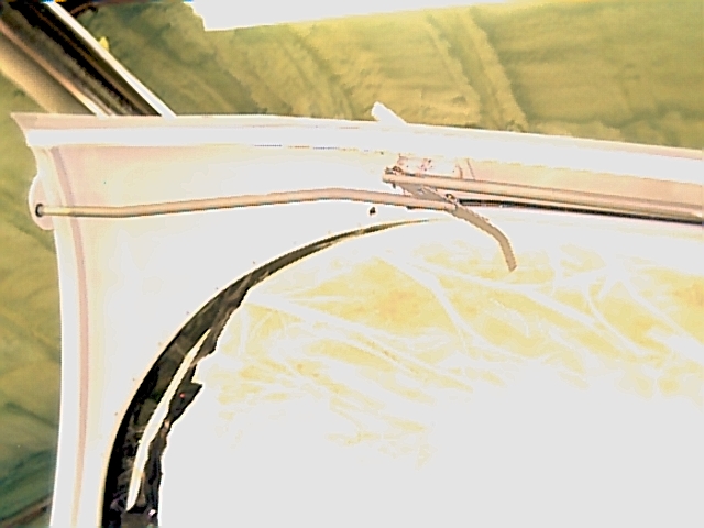
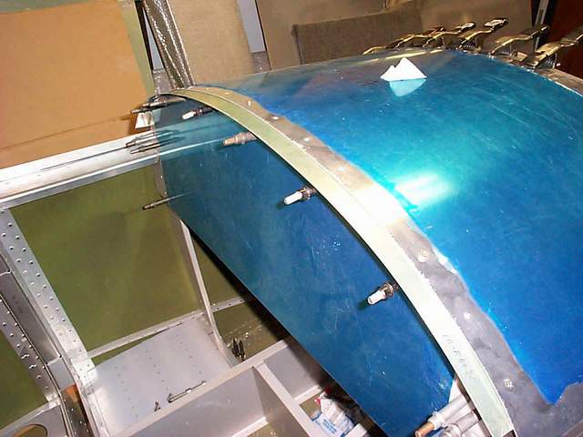
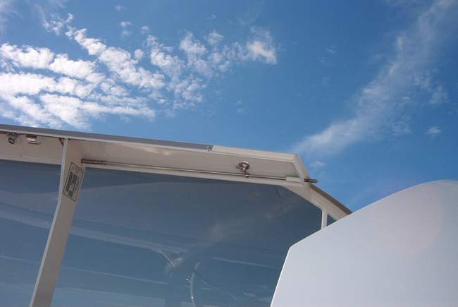
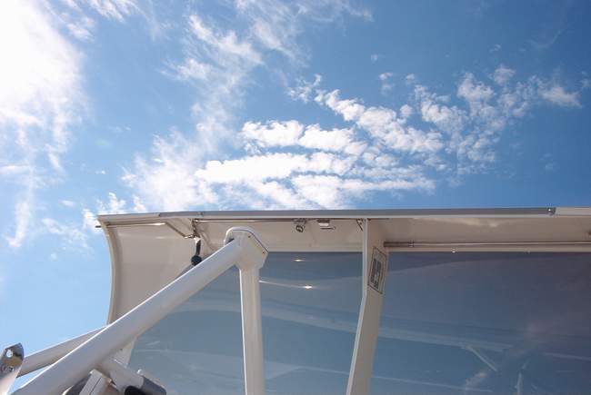
 The flopper canopy needs a seal along the right front edge. This is
similar to the nice one that Tom Martin has on his. I wish I'd seen his
before I trimmed the side skins! It could have been one piece. Doh!
Oh well, I'm building the Rocket for GO not for SHOW!
The flopper canopy needs a seal along the right front edge. This is
similar to the nice one that Tom Martin has on his. I wish I'd seen his
before I trimmed the side skins! It could have been one piece. Doh!
Oh well, I'm building the Rocket for GO not for SHOW!
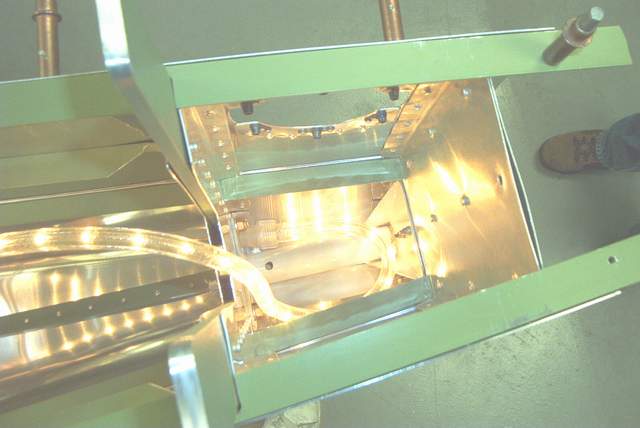
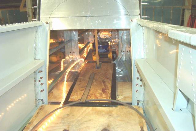
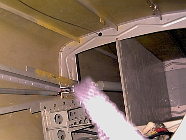
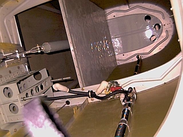
 The tail cone area. The rope light is a MUST HAVE item. Nice even
light, tough, and won't burn your skin. Get one at Walmart for $7 or so.
The tail cone area. The rope light is a MUST HAVE item. Nice even
light, tough, and won't burn your skin. Get one at Walmart for $7 or so.
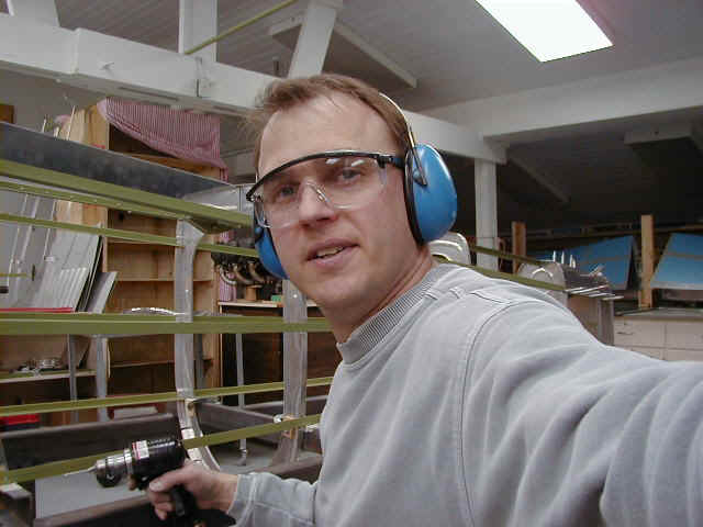
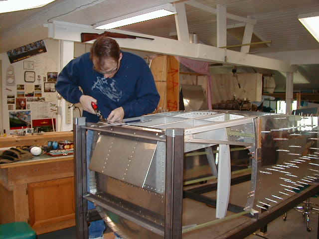
 Riveting with John Crabtree
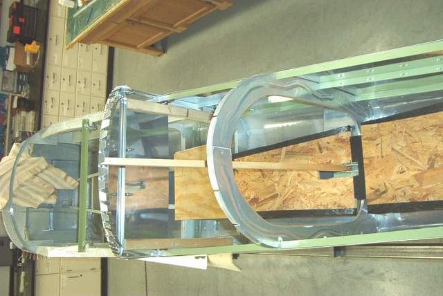
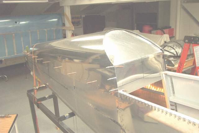
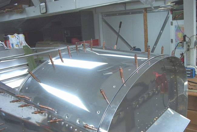
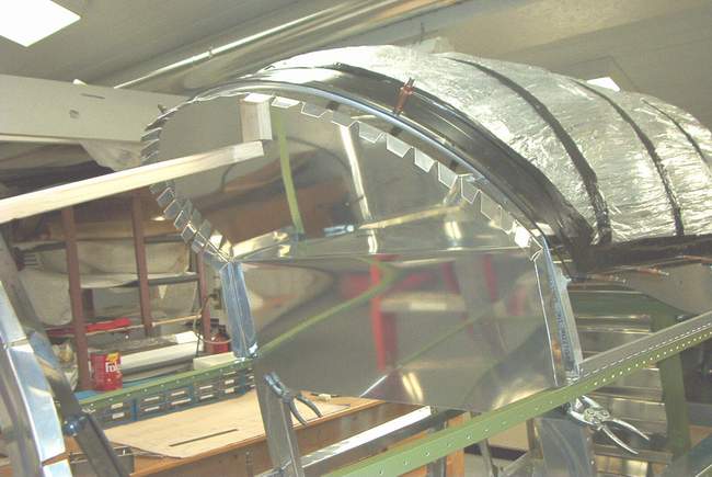
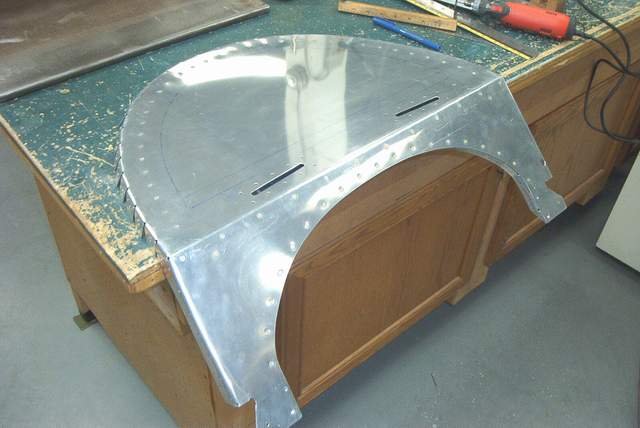
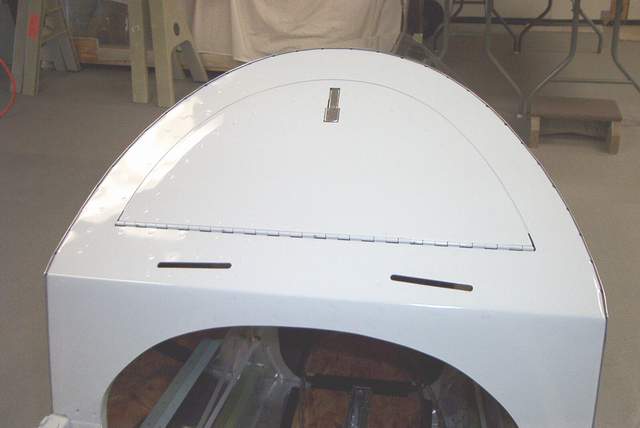
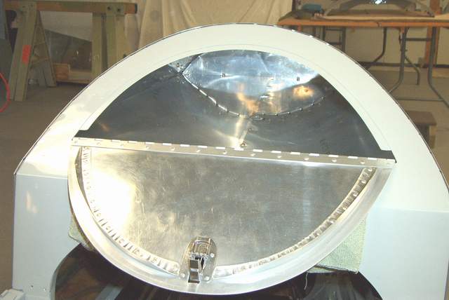
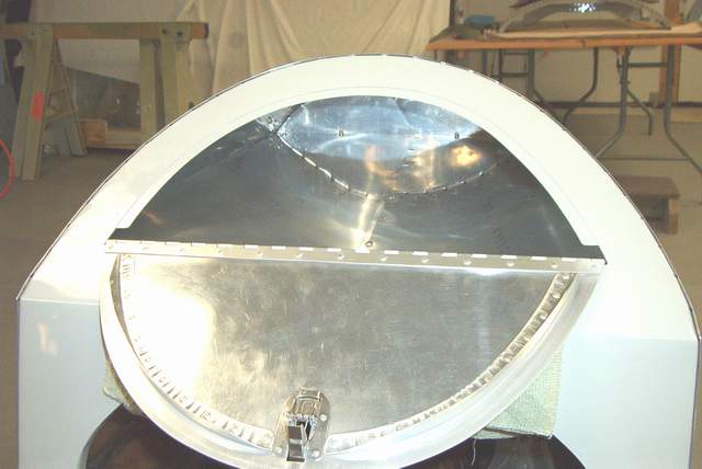
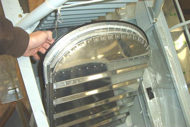
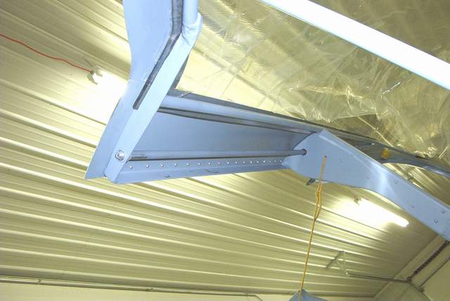
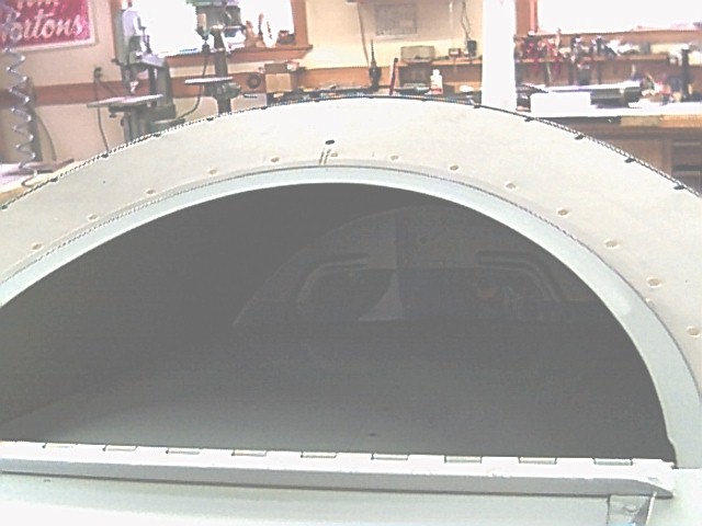
 Fitting the turtledeck. Much, much easier than I anticipated. It
sorta just fell into place with no problems.
Fitting the turtledeck. Much, much easier than I anticipated. It
sorta just fell into place with no problems.
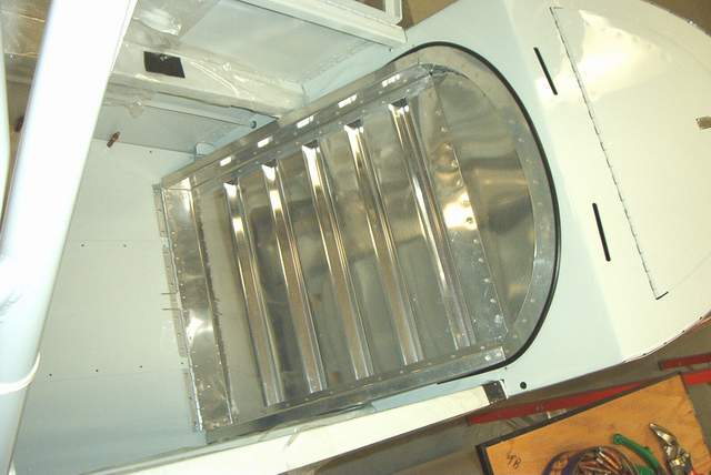
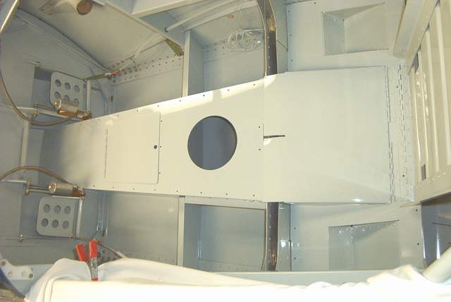
 The small baggage area above and behind the rear seat was shamelessly copied
from Tom Martin and others. It is quite a bit of work to design, fab, and
install. But you do get to lay on your back and get aluminum shavings in
your eyes, ears, nose, and mouth while doing it. But it turned out great
and I am very pleased. It should be very useful.
The small baggage area above and behind the rear seat was shamelessly copied
from Tom Martin and others. It is quite a bit of work to design, fab, and
install. But you do get to lay on your back and get aluminum shavings in
your eyes, ears, nose, and mouth while doing it. But it turned out great
and I am very pleased. It should be very useful.
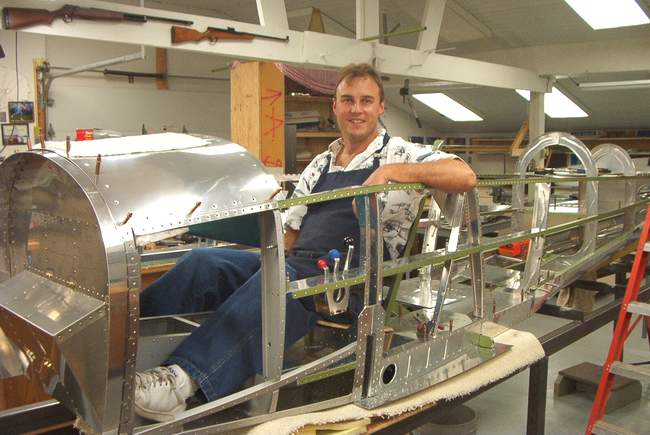
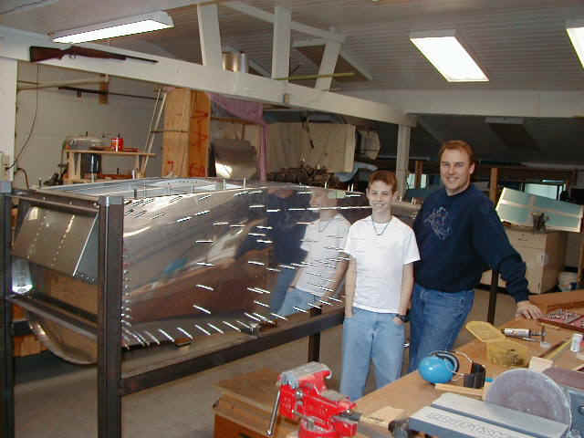
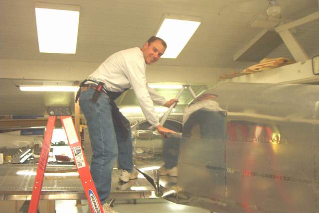
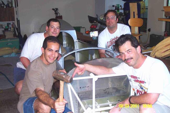
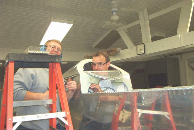 This is a great shot that fully captures in insanity of building your own plane.
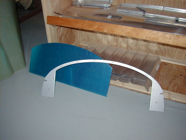
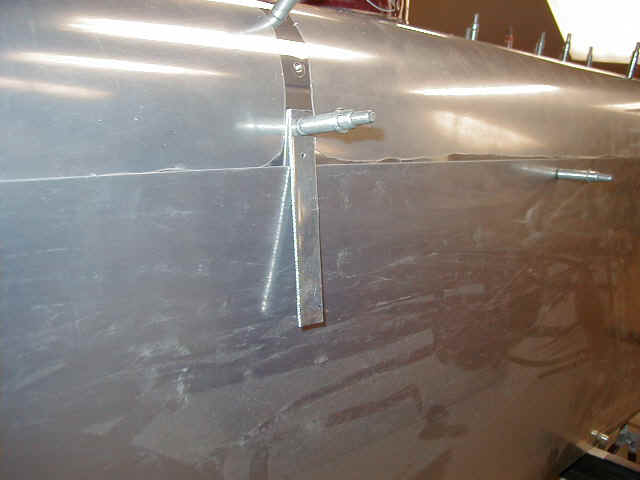
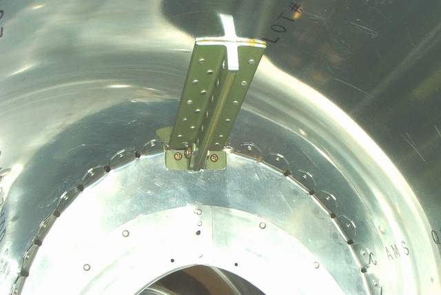
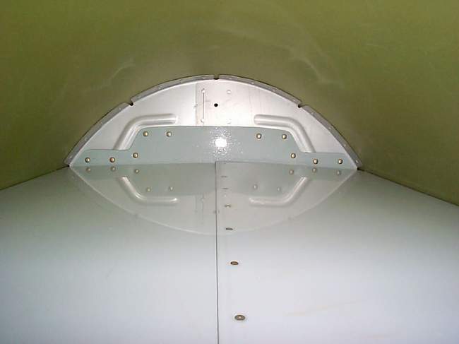
 RV-6 style forward longeron gusset.
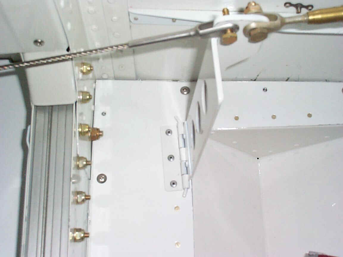
 I modified my rear seat shoulder harness attach points. A single point
system that will use 1/8" SS cable to attach to the shoulder harness. My
engineer buddy did some calcs and is convinced that it is at least as strong as
any in the RV's. I hope I never find out.
I modified my rear seat shoulder harness attach points. A single point
system that will use 1/8" SS cable to attach to the shoulder harness. My
engineer buddy did some calcs and is convinced that it is at least as strong as
any in the RV's. I hope I never find out.
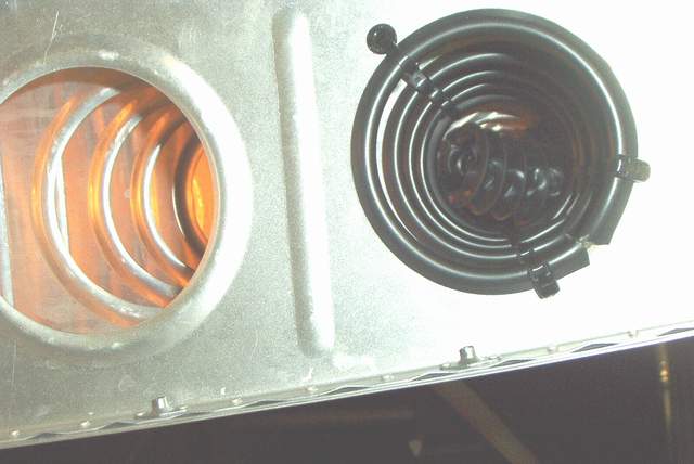
 NACA vents. There's one on each side. I added brass mesh, ProSealed over the
rear outlet to help keep critters out, even though it will cut down on airflow
slightly. I'll probably only get 9,837 CFM through it at 200 mph according to my
guesstimates.
NACA vents. There's one on each side. I added brass mesh, ProSealed over the
rear outlet to help keep critters out, even though it will cut down on airflow
slightly. I'll probably only get 9,837 CFM through it at 200 mph according to my
guesstimates.
 1-14-2003: The fuselage metalwork is done!!! Woo
hoo!
1-14-2003: The fuselage metalwork is done!!! Woo
hoo!
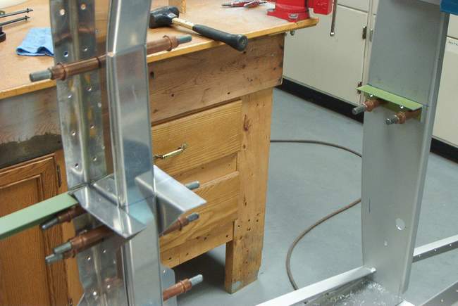
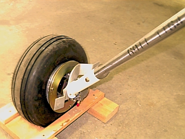
 Temporary gear legs until the Indy mount is painted and ready.
 2-18-2003: The Indy mount successfully installed.
Installation of the new mount is described in detail on the "Engine mount"
page on this website.
2-18-2003: The Indy mount successfully installed.
Installation of the new mount is described in detail on the "Engine mount"
page on this website.
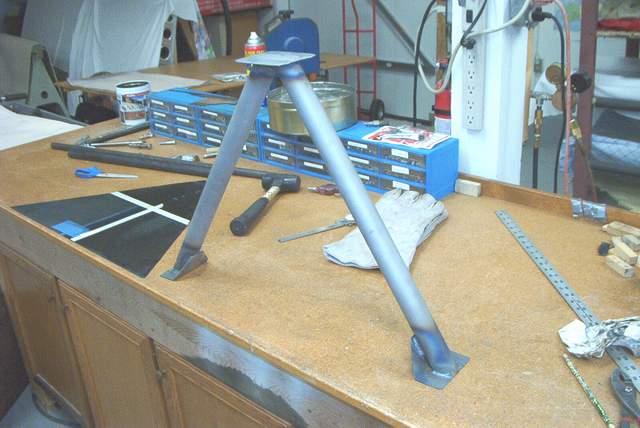
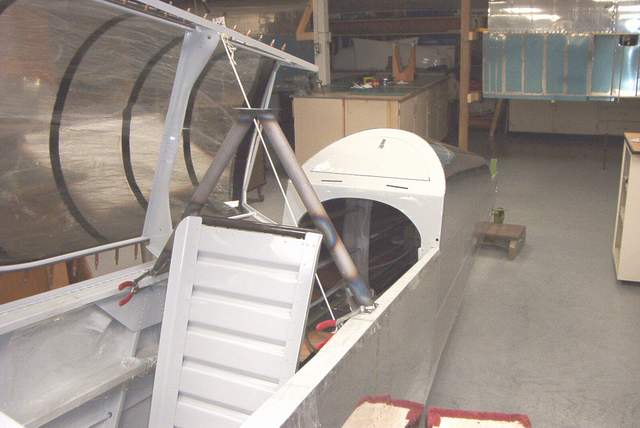

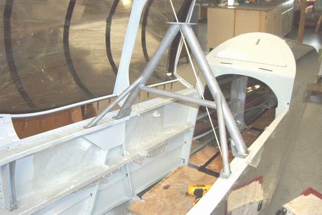
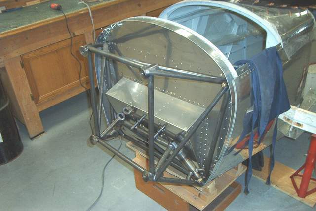
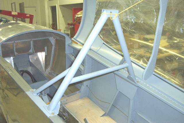
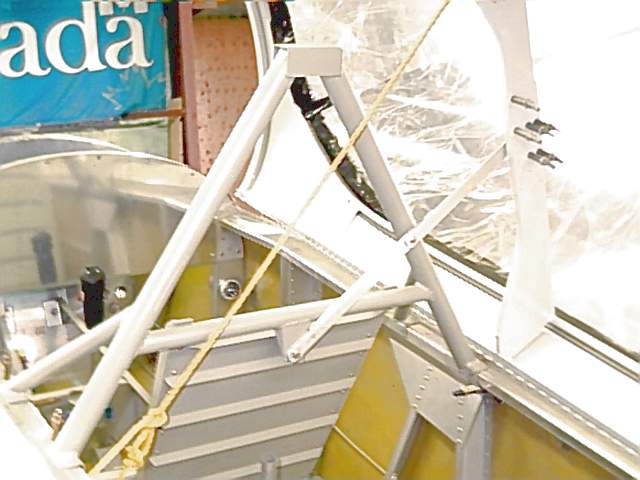
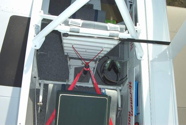
The next project was the rollbar fabrication. I used RV-4 blueprints as a general guide. Cutting and welding steel tubing is not something that I do every day. Nonetheless, the rollbar turned out fine. The first picture shows a large black triangle. It is x-ray film that my wife gets from work. I used it to make a template to ensure that the roll bar would fit inside the closed canopy. Very important. The 4" x 4" plate on top of the rollbar serves as a very convenient spot to mount a GPS antenna. There is a hole in the base of the rollbar for the antenna wire to pass up through the tubing. The plate also would help prevent the rollbar from sinking into soft ground if the plane were upside down..... I KNOW THIS CAN HAPPEN. ASK ME HOW I KNOW SOMETIME!! You'll see the same thing on 1930's military planes... a rollbar with a plate on top.
 4-7-03:
I threw away the fiberglass seat top and made this one from aluminum.
Fits perfectly. The upper edge is finished with a strip of door edge type
material and the rivet bucktails are covered with a soft piece of weatherstrip
foam.
4-7-03:
I threw away the fiberglass seat top and made this one from aluminum.
Fits perfectly. The upper edge is finished with a strip of door edge type
material and the rivet bucktails are covered with a soft piece of weatherstrip
foam.
1-6-04: I got the urge to make the seat upholstery.... but wait! I need seats first.
 Here I am deburring the front seat pan. If you think that this is
exciting, you probably need to get a life. OTOH, that cordless screwdriver
that I modified to use for deburring is kinda cool.
Here I am deburring the front seat pan. If you think that this is
exciting, you probably need to get a life. OTOH, that cordless screwdriver
that I modified to use for deburring is kinda cool.
 The front seat pan was CAD designed. In this case CAD is short for
"Computers Are Dumb." So, I used my eyeball instead and some .032 sheet.
Soon, I had a perfectly acceptable butt support.
The front seat pan was CAD designed. In this case CAD is short for
"Computers Are Dumb." So, I used my eyeball instead and some .032 sheet.
Soon, I had a perfectly acceptable butt support.

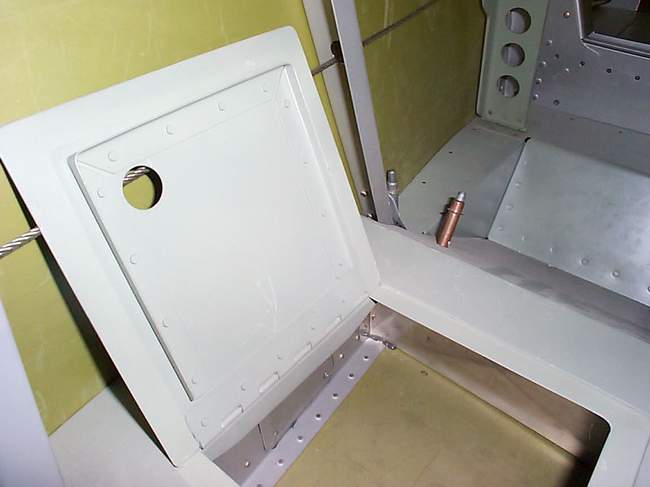
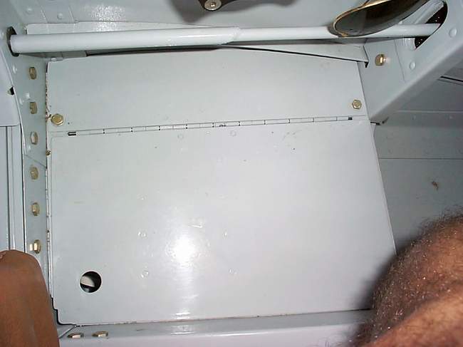
 The front seat pan installed. Like everywhere else that I can, I used
piano hinge so I can remove it quickly. It also folds up in case I want to
hide my outdated sectional charts during the ramp check. LOL. More later
after I take pictures of the back seat pan and crotch strap fittings.
The front seat pan installed. Like everywhere else that I can, I used
piano hinge so I can remove it quickly. It also folds up in case I want to
hide my outdated sectional charts during the ramp check. LOL. More later
after I take pictures of the back seat pan and crotch strap fittings.
 More pictures of the front seat pan, including how it folds upward. The
entire seat can be removed in about 5 seconds. This is handy for those
times when you're gonna work under the panel. Or you can remove those 48
screws that hold the boot cowl on and risk scratching your paint.... NO THANKS!
Thankfully, I'm still thin enough and limber enough to just dive under the
panel. It helps to take the control stick out also when panel diving.
More pictures of the front seat pan, including how it folds upward. The
entire seat can be removed in about 5 seconds. This is handy for those
times when you're gonna work under the panel. Or you can remove those 48
screws that hold the boot cowl on and risk scratching your paint.... NO THANKS!
Thankfully, I'm still thin enough and limber enough to just dive under the
panel. It helps to take the control stick out also when panel diving.
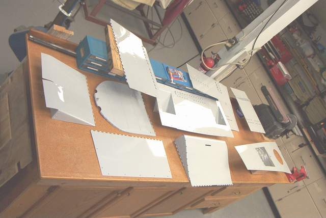 The interior parts with fresh paint on them... a rarity in January. We had
a warm spell with temps up to about 65 degrees so I painted everything that I
could.
The interior parts with fresh paint on them... a rarity in January. We had
a warm spell with temps up to about 65 degrees so I painted everything that I
could.
 The rear seat crotch strap fitting is made from a piece of 1/8" x 1" angle.
It is riveted to the removable floorboard. When permanently installed it
is also bolted to the seat rib longerons.
The rear seat crotch strap fitting is made from a piece of 1/8" x 1" angle.
It is riveted to the removable floorboard. When permanently installed it
is also bolted to the seat rib longerons.
 The rear seat pan is made from .032 aluminum. It was also carefully CAD
(computers are dumb) designed by placing my butt in the back seat and taking a
WAG about what kind of shape was needed. My butt was very happy with this
shape. Flying is more fun when your butt is happy.
The rear seat pan is made from .032 aluminum. It was also carefully CAD
(computers are dumb) designed by placing my butt in the back seat and taking a
WAG about what kind of shape was needed. My butt was very happy with this
shape. Flying is more fun when your butt is happy.
As you can see, the top is NOT flat, but (butt.... he he, a pun) slightly S-curved. It should be quite comfortable when topped with a nice Temperfoam cushion.
Some people use a stack of cushions in this area, but (butt...he he I said "butt" again) I don't like that idea. The stack of cushions is often to soft, or too wobbly and feels unstable.
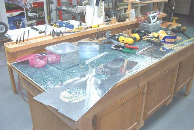

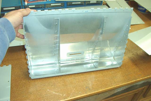
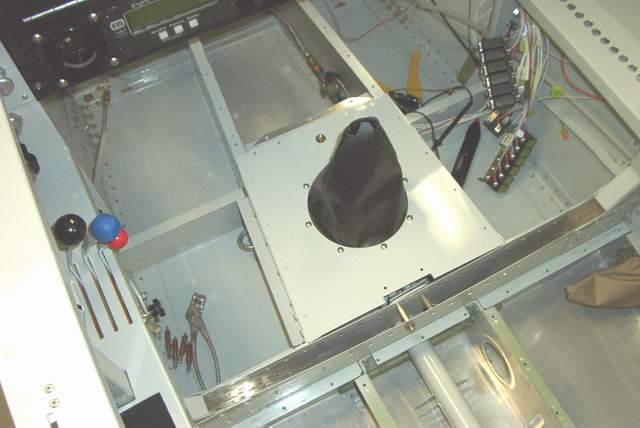
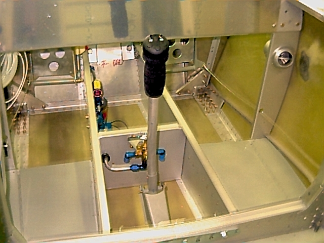
 The center console area simply cries out for a glove box. I had the same
thing on my RV-4 and it worked quite well. Here is the latest version.
It is 5"deep to allow room for fuel lines, etc. to pass beneath it. The
box itself was made from a SINGLE piece of folded .016 aluminum... just to show
off my mad skills with aluminum. Too bad I forgot to take a picture of it.
The center console area simply cries out for a glove box. I had the same
thing on my RV-4 and it worked quite well. Here is the latest version.
It is 5"deep to allow room for fuel lines, etc. to pass beneath it. The
box itself was made from a SINGLE piece of folded .016 aluminum... just to show
off my mad skills with aluminum. Too bad I forgot to take a picture of it.
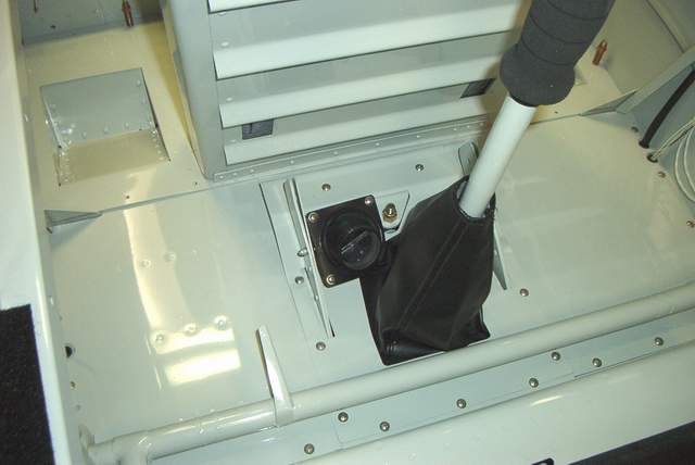
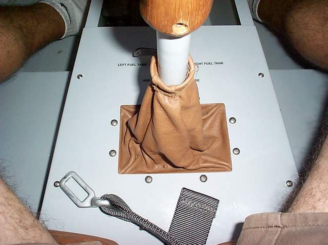
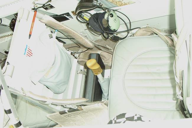
 Much later.... a shot with the front stick boot installed. The
boot is a EL CHEAPO brand from JC Whitney's shifter boot section. Works
fine.
Much later.... a shot with the front stick boot installed. The
boot is a EL CHEAPO brand from JC Whitney's shifter boot section. Works
fine.
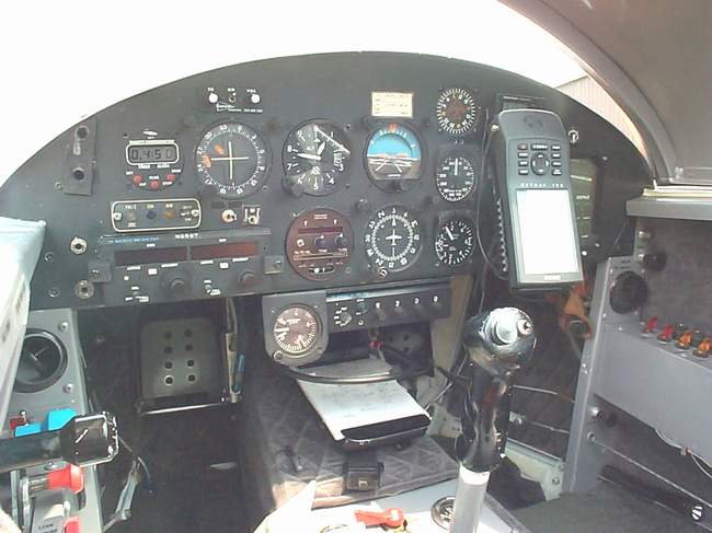
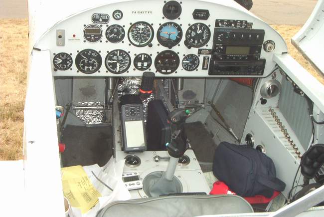
 Much, much later... the stick is bent so that it no longer hits the
instrument panel. This also makes it MUCH more comfortable to grip since
it was much too far forward before. No, it does not hit me in the belly
when pulled aft... but it is comfortably close just like you'd want it to be.
Much, much later... the stick is bent so that it no longer hits the
instrument panel. This also makes it MUCH more comfortable to grip since
it was much too far forward before. No, it does not hit me in the belly
when pulled aft... but it is comfortably close just like you'd want it to be.
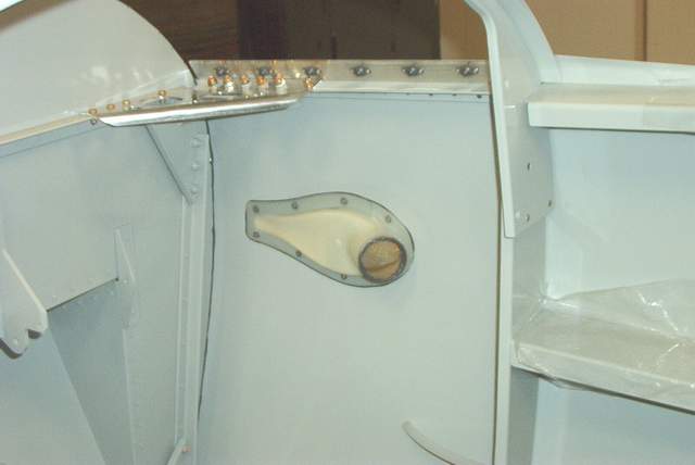
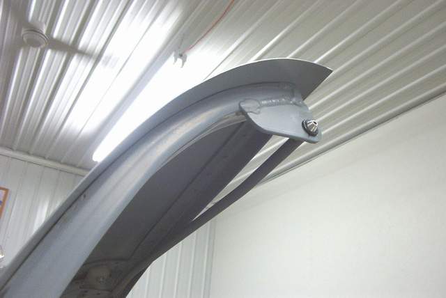
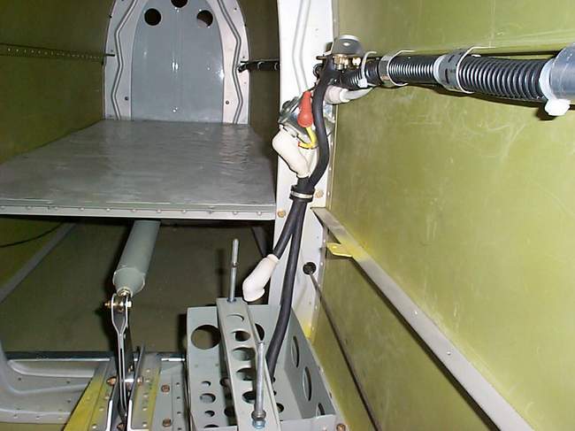
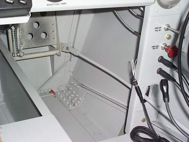
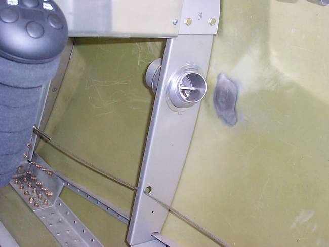
 5-05-04: The rear seat vent tube needs to pass
through a tight area. I used PVC pipe and heated the elbow to mash it a
bit so it would fit tightly against the sidewall.
5-05-04: The rear seat vent tube needs to pass
through a tight area. I used PVC pipe and heated the elbow to mash it a
bit so it would fit tightly against the sidewall.
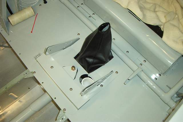
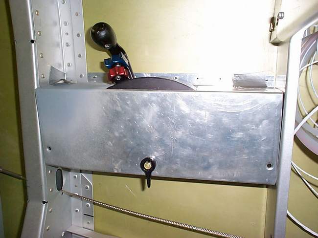
 A hodgepodge of parts to cover the stick hole. Several pieces of
shoebox cardboard gave their lives to make the templates for these pieces.
A hodgepodge of parts to cover the stick hole. Several pieces of
shoebox cardboard gave their lives to make the templates for these pieces.
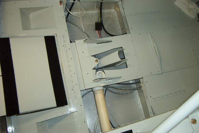
 The area in front of the stick support gets a simple bent aluminum sheet.
If you look REAL closely at the photo, you can see the small filler wedges that
cover the area just under and outboard of the seat belt attach brackets.
The area in front of the stick support gets a simple bent aluminum sheet.
If you look REAL closely at the photo, you can see the small filler wedges that
cover the area just under and outboard of the seat belt attach brackets.
 Then the main cover goes on.
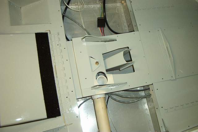 The smaller cover fills the front portion.
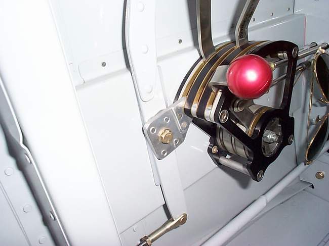
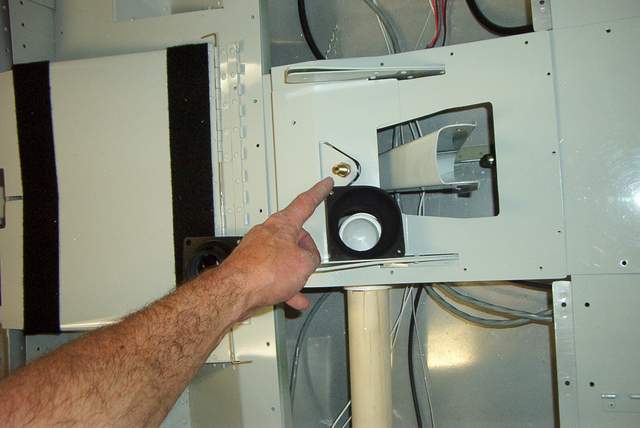 The vent adapter gets glued on with silicone (not shown) and a bolt through the
seat belt attach bracket.
The vent adapter gets glued on with silicone (not shown) and a bolt through the
seat belt attach bracket.
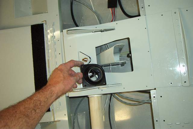
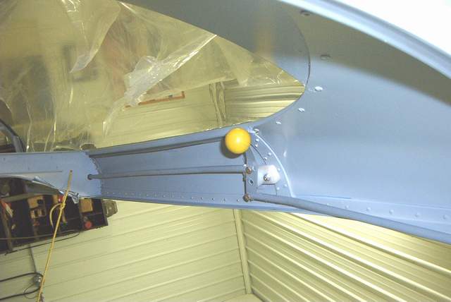
 The vent ball goes on last.
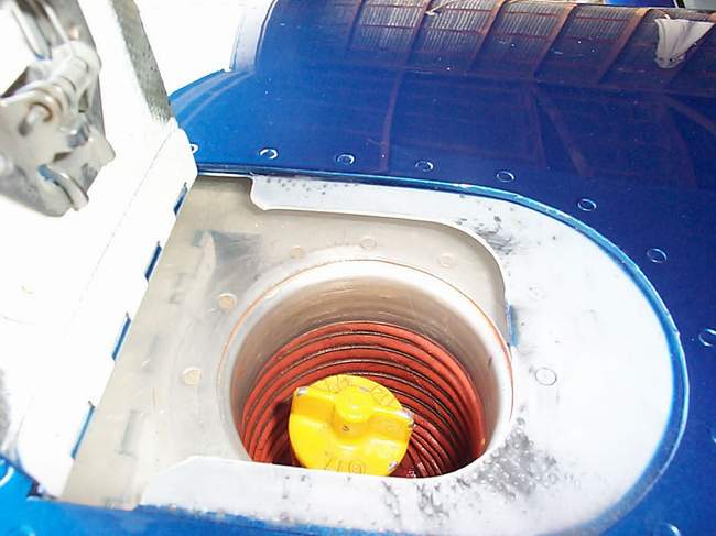
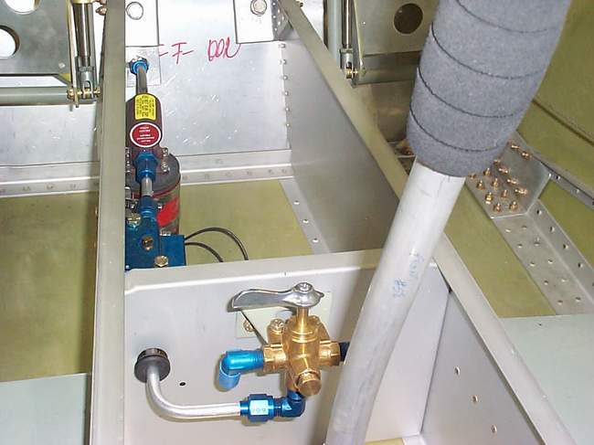
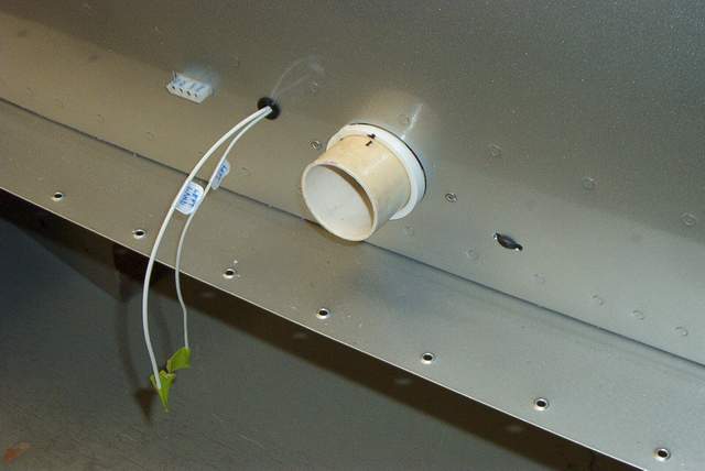 The attach point for the hose coming from the wing. You can see a PVC
ring, made from a spare PVC fitting, glued in place to prevent the PVC pipe from
moving.
The attach point for the hose coming from the wing. You can see a PVC
ring, made from a spare PVC fitting, glued in place to prevent the PVC pipe from
moving.
 And finally a shot with the rear boot installed. The boot is a EL
CHEAPO brand from JC Whitney's shifter boot section. Works fine.
And finally a shot with the rear boot installed. The boot is a EL
CHEAPO brand from JC Whitney's shifter boot section. Works fine.
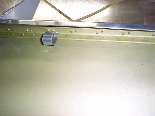
 Here's a shot looking into the wing where the vent hose runs. I
put door edge trim around the holes to prevent the hose getting cut or chaffed.
You can get the door edge trim at any automotive supplier. It will adhere
itself to the metal but everything is zip tied for added assurance that nothing
will come loose in this inaccessible area. You can't see it in the photo
but the hose clamp holding the hose to the NACA vent is also safety wired so it
can't go anywhere.
Here's a shot looking into the wing where the vent hose runs. I
put door edge trim around the holes to prevent the hose getting cut or chaffed.
You can get the door edge trim at any automotive supplier. It will adhere
itself to the metal but everything is zip tied for added assurance that nothing
will come loose in this inaccessible area. You can't see it in the photo
but the hose clamp holding the hose to the NACA vent is also safety wired so it
can't go anywhere.
If I were doing this area again, I'd consider using 2" lightweight PVC pipe instead of the hose. I'd use a short length of hose to attach the PVC pipe together at the wing root.... or I might simply use a good grade of tape wrapped around the joint and zip-tied. Vince Frazier *end of comment*
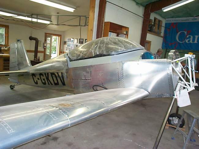
 4-21-03: I have the wings installed now.
More about that on:
http://www.usi.edu/science/chemistry/vfrazier/Everything%20else.htm
4-21-03: I have the wings installed now.
More about that on:
http://www.usi.edu/science/chemistry/vfrazier/Everything%20else.htm
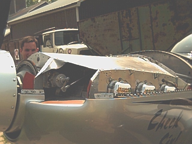
Jim Wining's F-1 project: I visited Jim Wining's F-1 on 2-1-03. Jim is doing extremely nice work as you can see in the pictures below. Jim is using Craig LeFevre's engine baffles, Vetterman exhaust, and a Suzuki alternator from AutoZone.
 His canopy frame is 10x nicer than mine. (My excuse is that since I don't
have a QB kit I have become too impatient and cosmetics have suffered.)
His latch mechanism is very good too. I forgot to get a picture of the
latch receptacle on the left side of the instrument panel. It has two
holes, one for taxi ventilation and one for flight.
His canopy frame is 10x nicer than mine. (My excuse is that since I don't
have a QB kit I have become too impatient and cosmetics have suffered.)
His latch mechanism is very good too. I forgot to get a picture of the
latch receptacle on the left side of the instrument panel. It has two
holes, one for taxi ventilation and one for flight.
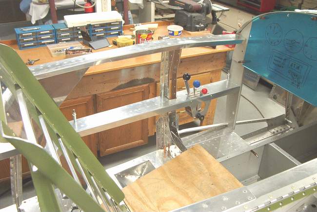
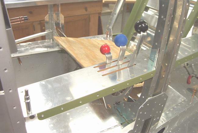
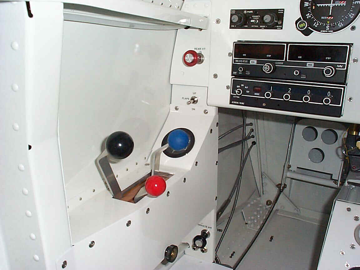
 Jim made his own throttle quadrant. The rod end forks are riveted to the
throttle levers to allow the unit to be a narrow as possible. The rear
seat throttle is connected via the push tube.
Jim made his own throttle quadrant. The rod end forks are riveted to the
throttle levers to allow the unit to be a narrow as possible. The rear
seat throttle is connected via the push tube.
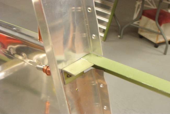
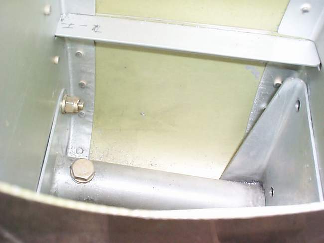
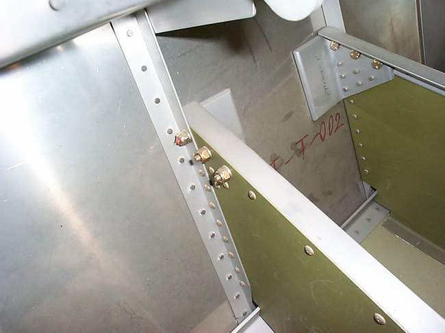
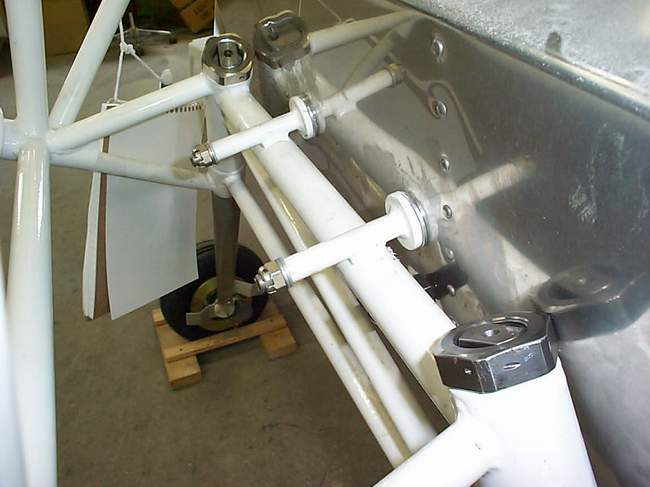
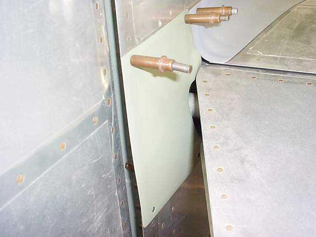
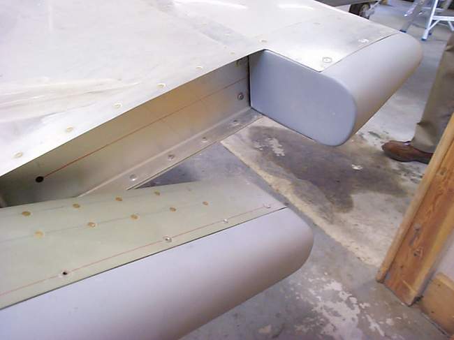
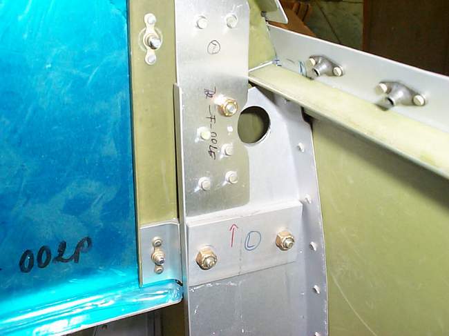
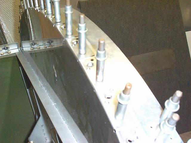
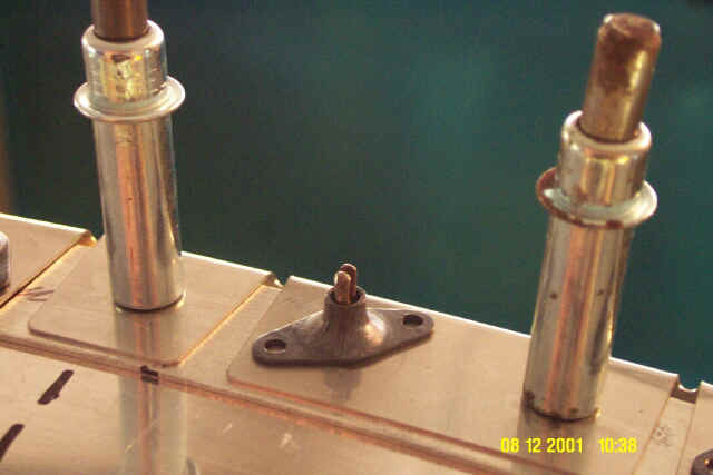
 The forward tank attach point.
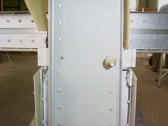
 Rudder stops.
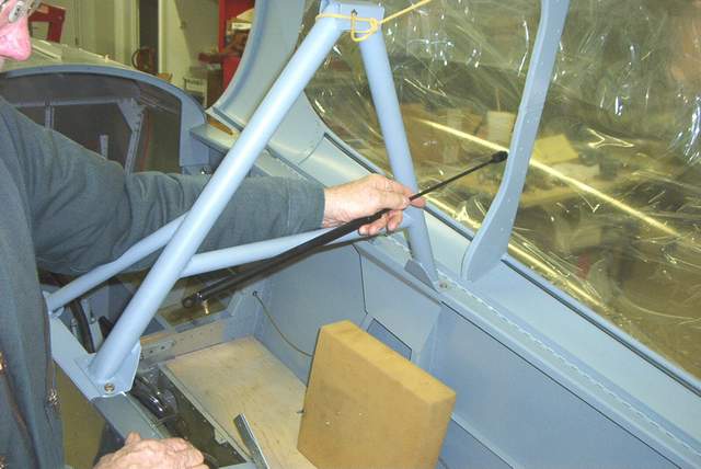 Jim made his own RV-4 style rollbar (very important IMHO). The second
picture shows the gas strut from a Chevy Blazer rear hatch. If you look
closely you can see a bicycle tire valve soldered to the left end of the strut.
Jim released the excess pressure of the stock strut and plans to use a nitrogen
bottle or strut pump to put in pressure appropriate for a Rocket canopy.
Jim mentioned that when the crossbar was welded to the rollbar the sides pulled
in about 1/4" at the cockpit rail. With that in mind, I think I'll weld
the feet on last when I build my rollbar.
Jim made his own RV-4 style rollbar (very important IMHO). The second
picture shows the gas strut from a Chevy Blazer rear hatch. If you look
closely you can see a bicycle tire valve soldered to the left end of the strut.
Jim released the excess pressure of the stock strut and plans to use a nitrogen
bottle or strut pump to put in pressure appropriate for a Rocket canopy.
Jim mentioned that when the crossbar was welded to the rollbar the sides pulled
in about 1/4" at the cockpit rail. With that in mind, I think I'll weld
the feet on last when I build my rollbar.
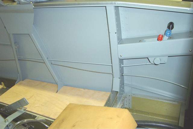
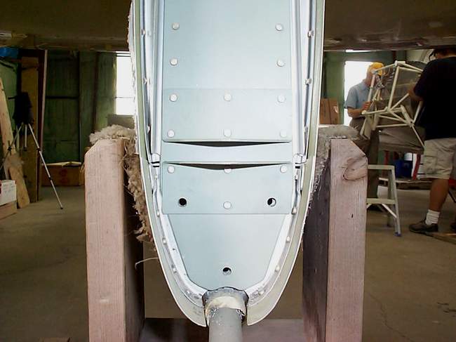
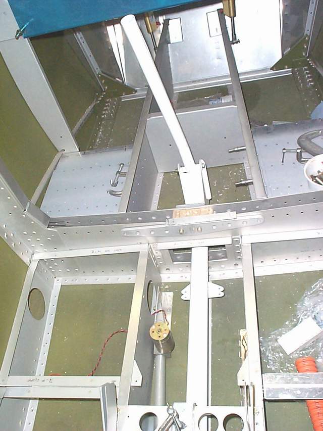
 Floor area.
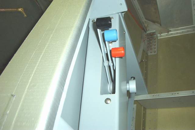
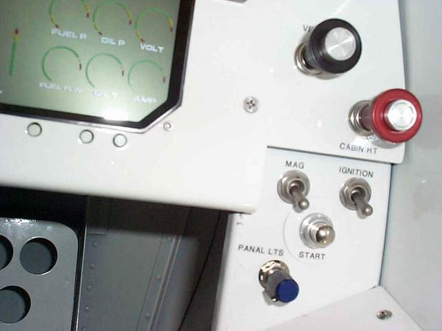
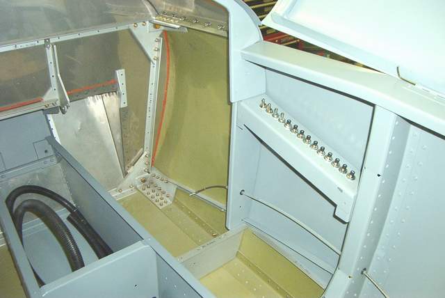 Breaker panel.
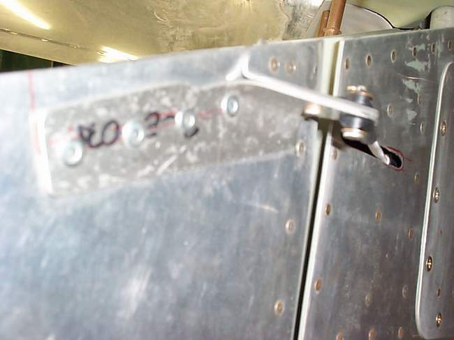
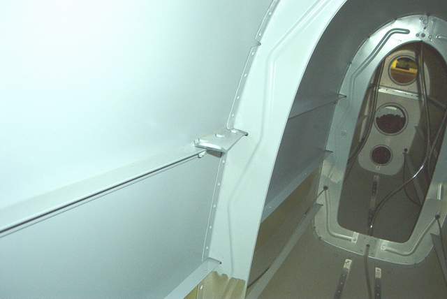 Rear seat shoulder attach fitting. Completely different from mine.
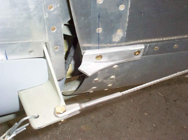
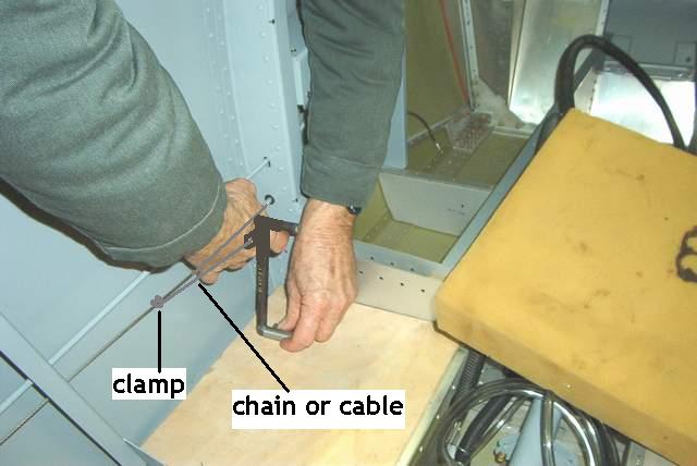 The rear seat rudder pedals are designed to attach to the rudder cables with a
short length of chain. They fold down flat to the floor when not in use.
The rear seat rudder pedals are designed to attach to the rudder cables with a
short length of chain. They fold down flat to the floor when not in use.
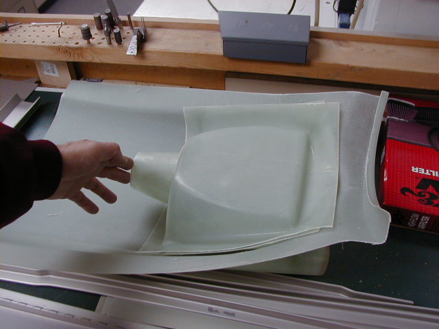
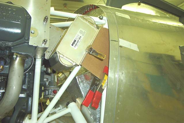 Oil cooler installation cardboard templates.
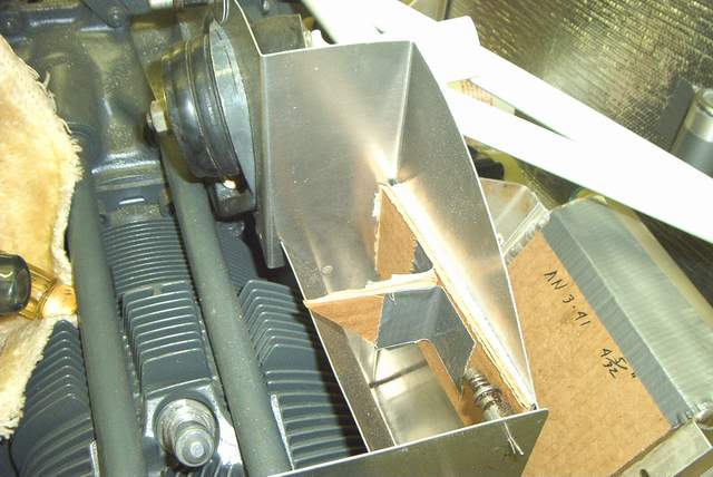
 Oil cooler airflow gate mockup.
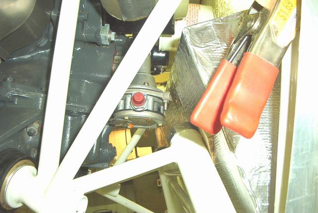 The fuel pump overflow fitting is made from a short plug. The plug is
tapped for a barbed hose fitting.
The fuel pump overflow fitting is made from a short plug. The plug is
tapped for a barbed hose fitting.

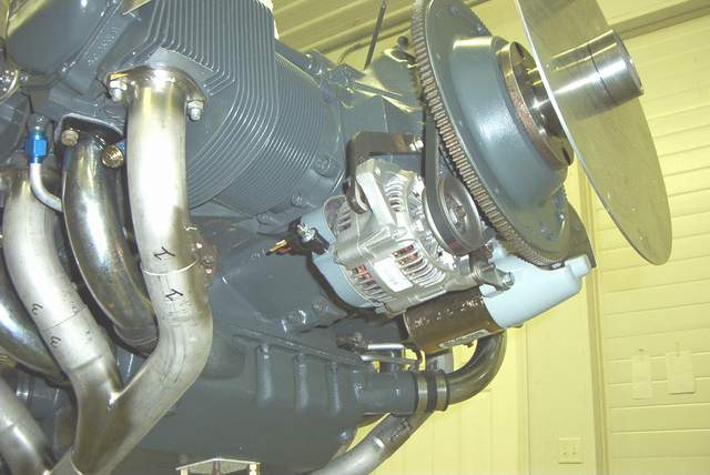 The Suzuki alternator and bracket.

 The spinner template for installing the cowling.
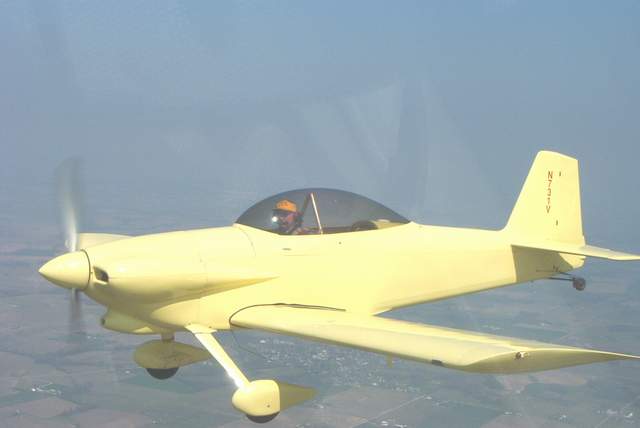 Jim Wining's flying about 6" from Bob Japundza's RV-6. Jim's RV-4 is very
sensitive to turbulence... it just won't stay right side up for very long.
;-)
Jim Wining's flying about 6" from Bob Japundza's RV-6. Jim's RV-4 is very
sensitive to turbulence... it just won't stay right side up for very long.
;-)
ELT and Trutrac installation: from Bob Hayner
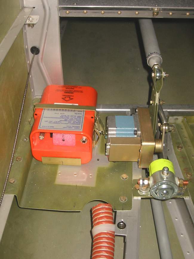
 ELT
antenna installation.
ELT
antenna installation.
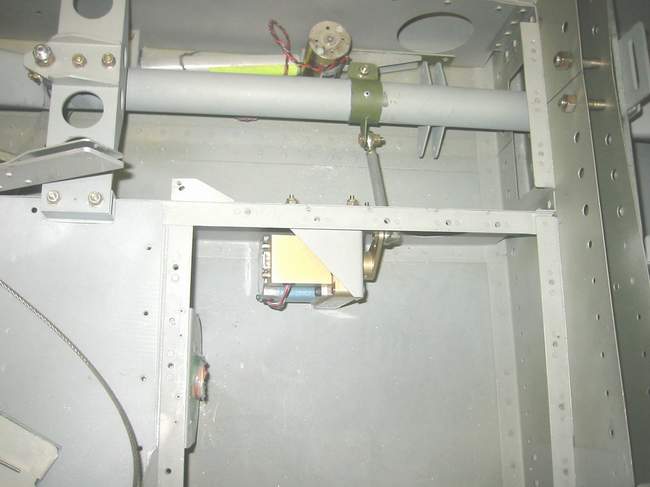
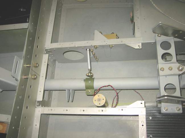 Trutrac installation.
 Aileron boot to seal out drafts.


 Here's what I did in the center, sort of ala Bob Gross.
Bob Hayner
Here's what I did in the center, sort of ala Bob Gross.
Bob Hayner
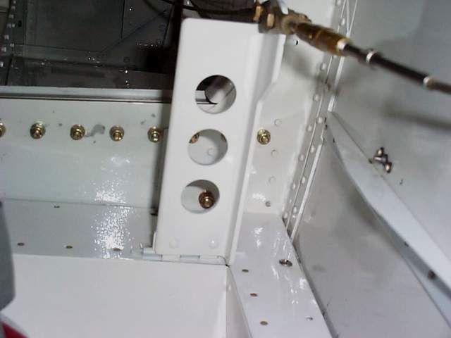
Panel installation: from Thomas Linscomb
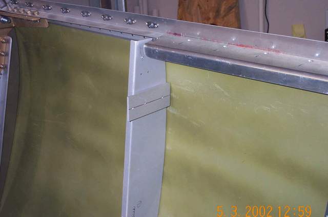

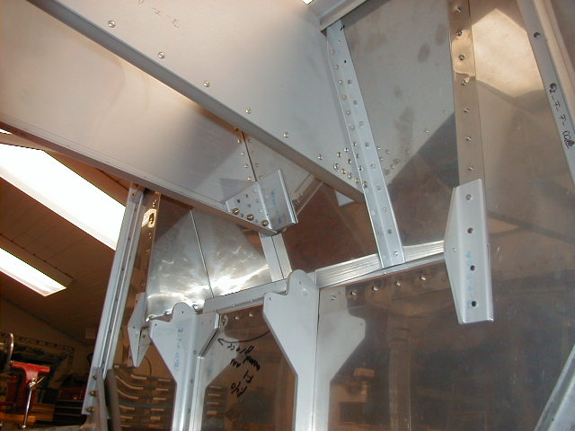
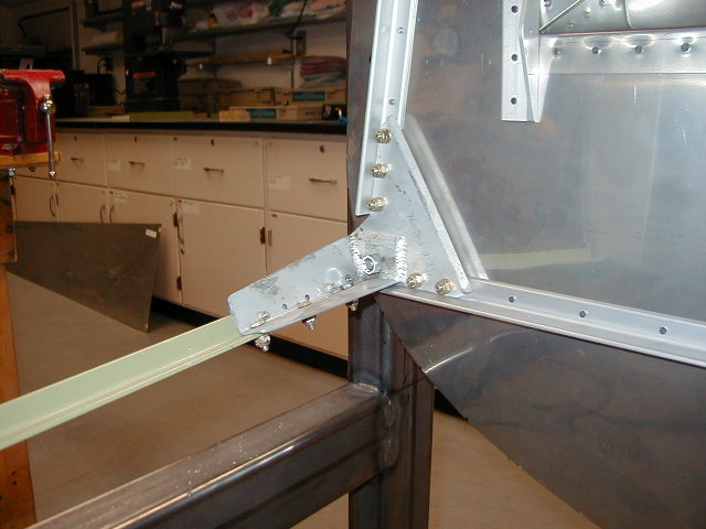
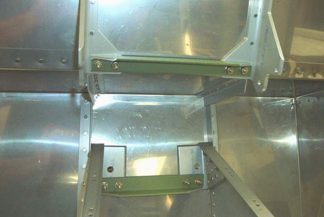
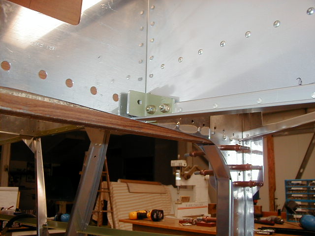
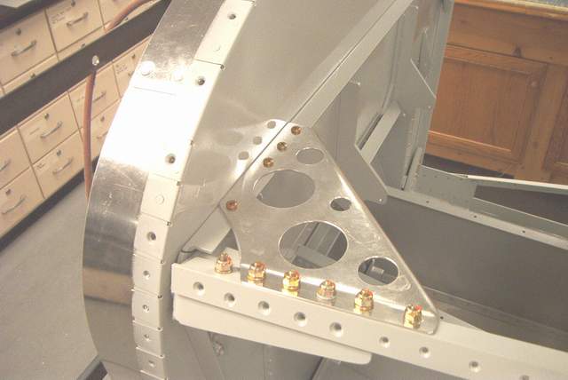
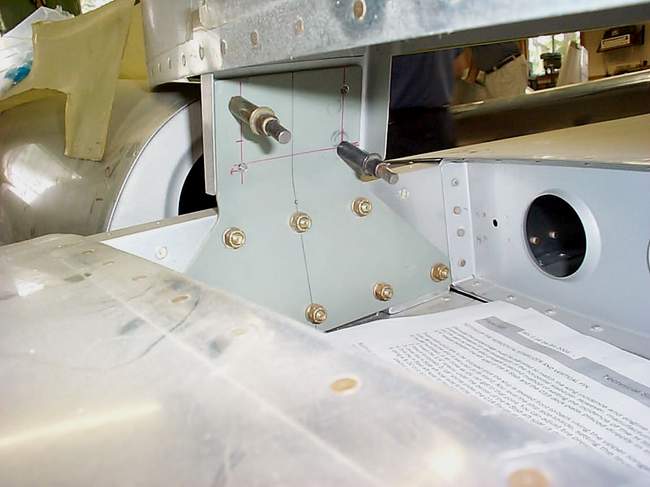
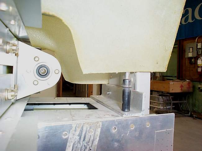
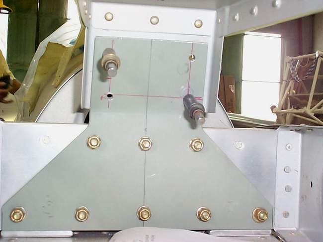
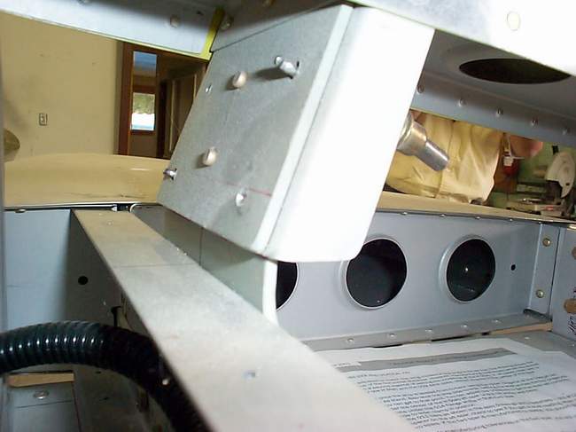
A: AHA!! OK: the wedgies you found taped to the bottom of the ship are the ones that go on the back of the #2 bulkhead to keep the fasteners 90 deg to the surface they go thru (in other words, the wedge gives the back side of the fastener a 90 deg angle to tighten against). I consider these optional parts. The angle brace for the fwd end of the cockpit rail will attach to the inst panel support bulkhead only, whether it is on the top or the bottom side. Mark Frederick
Ok, just so that we are all talking about the same parts and pieces. Each side has a #2 bulkhead, a instrument panel frame, two machined wedges, a upright flat piece (gusset) , and a small .032 thou angle the holds the cockpit rail to the rest of the parts.The gusset is riveted to the #2 bulkhead on the bottom before the panel frame is put in place. The panel frame is then put in place and the gusset is riveted to the panel frame using the upper portion of the gusset. I used two flush rivets on the top and I think four rivets on the bottom. The two wedges are used on the bottom of the panel frame. One between the panel frame and the #2 bulkhead, the other on the forward face of the #2 bulkhead. This is a very nice assembly as the two wedges placed properly mean that the bolts or screws that you put through here will have a "flat" surface for the head and the nut of the bolt. Someone put a lot of thought into that one! This is a good example of the things I really like about this kit.
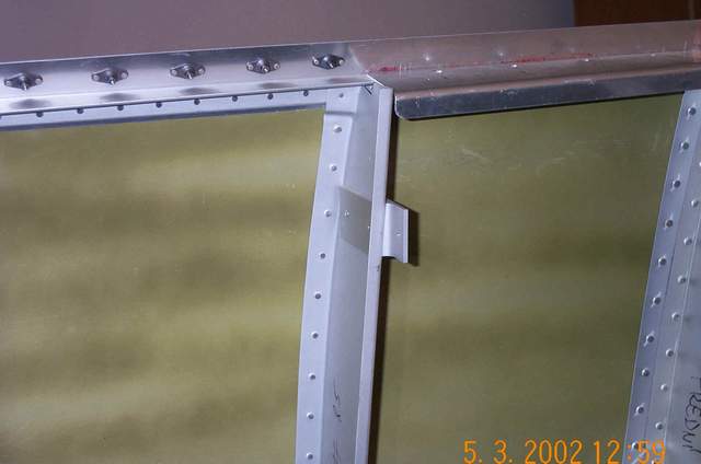
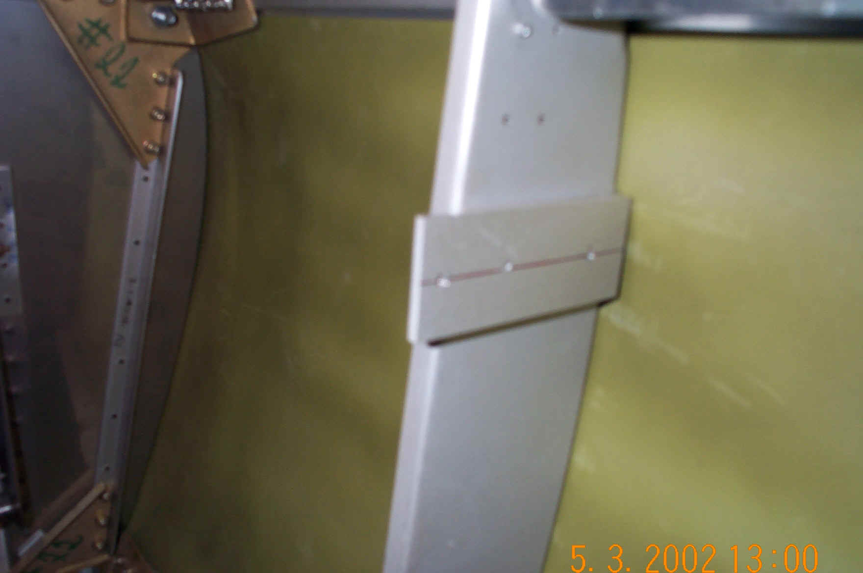
Now I fasten the cockpit rail to the rest of the parts using a little piece of .032 angle under the rail. I fasten it to the rail using two flush rivets. The other side of the angle is drilled and screwed/bolted to the panel frame/#2 bulkhead/ gusset assembly. In the pictures Mark shows the angle on top of the cockpit rail and we did one plane that way and the other with the angle under the rail. It looks better under the rail. If you did not get a nice cut/fit on your cockpit rail then put in on the top to hide the gap!!! Does that make sense? Tom Martin
Miscellaneous F-1 Project Photos
 Lui gives a lesson on proper tool selection.
7-08-2002: These are pics I took at Tom Martin's 2nd annual Canadian Sunset fly-in. The fly-in was great. I highly recommend it. The info absorbed during the fly-in was invaluable.


Here's some more miscellaneous shots...


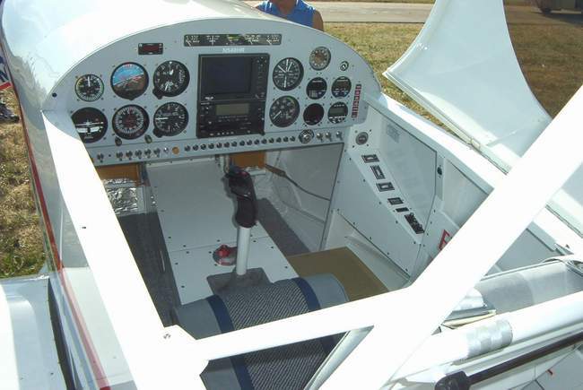
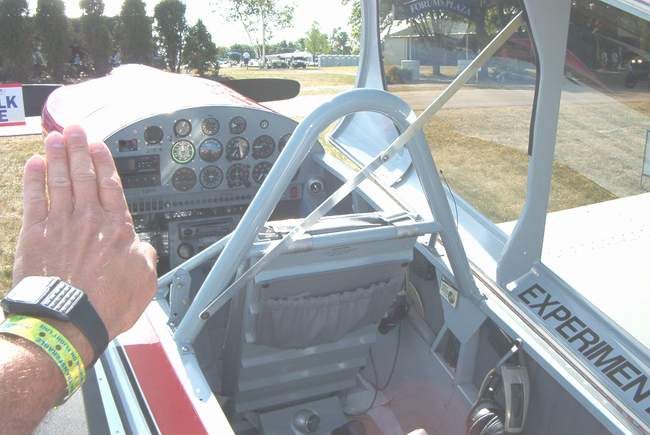
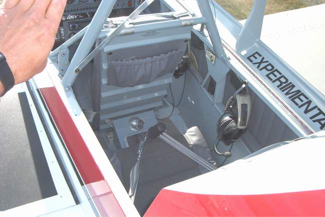
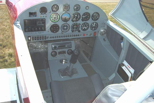
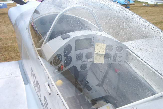
Cockpit shots from Oshkosh 2002


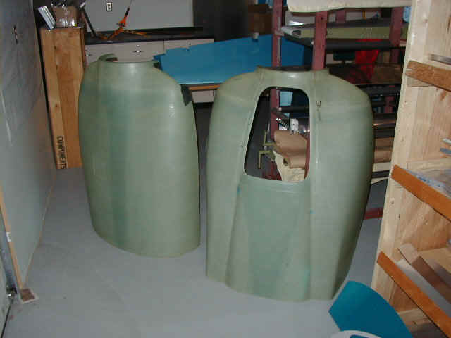
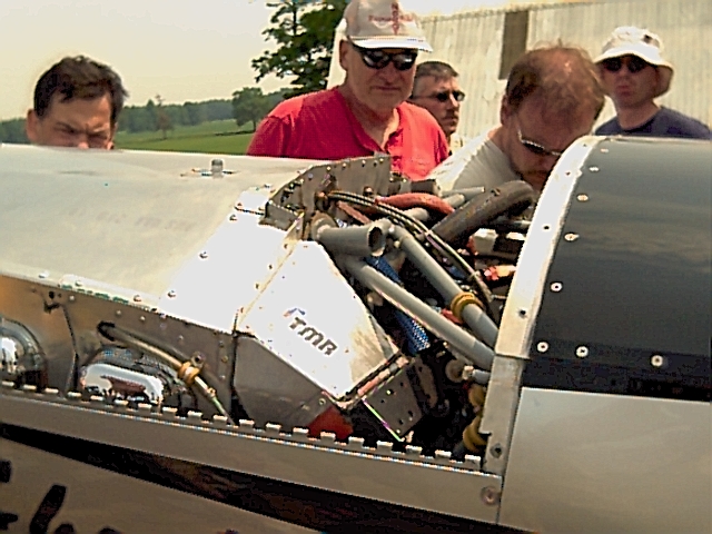
Mike Horton's Rocket Project


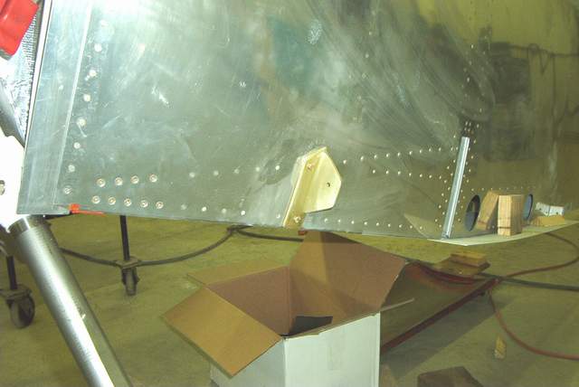
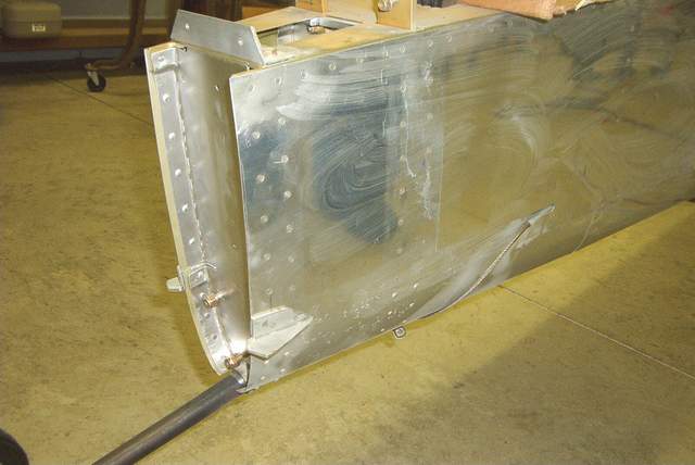
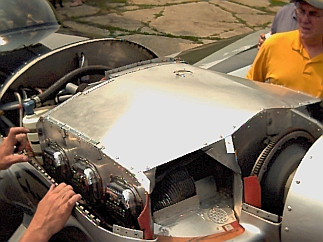
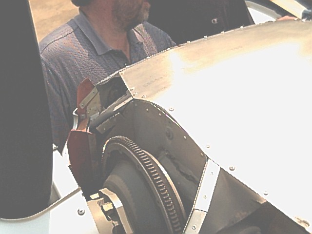
The photos above show Mike Horton's project. Mike is using an F-1 cowl on his HRII. As you can see in the photos, the firewall has been widened by adding material to each side. The HRII parts behind the firewall complicate matters and will require a "double-hull" behind the firewall. Contact Mike at mjhorton@easilink.com
2-6-03: Mike sent a pic of his slider. Looks good. I suppose it means that he has the front fuselage mods under control if he's got a canopy installed.
Mike had this to say about his mods: "I think the angle of The F-1 gear puts more weight on the tailwheel. I wasn't too worried as my engine is lighter as I'm not using any mags or vacuum pump and I have a redundant GR Battery in the aft baggage. However I have a Christen/Airwolf oil system. It all mounts onto the firewall.The mod should add only minimal weight, and the gusset will even help beef up the lower stringer as it ties into the side/bottom skin. (now I'm an aircraft engineer, lots of luck!)
If you know anyone that may be looking for a nice 4 let me know. I hate selling it but I need a panel, finish engine overhaul, and all that stuff. You know, we've got to stimulate the economy even though we're broke !
Thanks, Mike" *end of comment*Larry James comments: I've ended up making quite a few changes (good or bad is arguable :-). Given that John's parts (no malice intended at all here) and Mark's parts don't fit exactly (mixing airplanes, again no malice :-) I've ended up using all as templates to get me close; so most fuselage parts are built new. The main longerons started life as .125 x 1.125 x 1.100 2024-T351 extrusion. The forward end was left full size to accommodate bolting to the firewall weldments and the remainder was tapered down clear to the aft-most bulkhead; where they are again full size to accommodate bolting to the structure back there. A lot of work, much added structural integrity, and a tiny bit more weight (grams). I've also made new aft bulkheads to re-loft the rear of the fuselage so that the sides blend into the rudder (looking at all RV's, the fuselage is about 1/2" to3/4" wider on each side than the rudder). Again, lot's of work, probably no performance gain, and a tiny detail addressed. These are but two examples. You can see why this thing is taking me longer than it could. I'm getting antsy though, and want to fly. Larry E. James
General Construction Comments:
Check the wing section for more photos and comments regarding the F404 bulkhead. Vince Frazier *end of comment*
More input: The 23 1/2" dimension at the longeron at # 7 and the vertical dimension of 23 " is an important location to make all the parts supplied by Harmon Co. fit without a lot of modifying. John Harmon *end of comment*
When working on the firewall make sure you deburr all the edges. The .018 stainless is a very good meat slicer. *end of comment*
The main longerons Vans supplies for the fuselage aren't long enough, You can do four things, one is to stretch it longer (just kidding), two is to have a piece welded on (yuck!), three is to splice in another section with bolts, which is a major pain. The best idea is to purchase the proper length of .125 x 3/4" x 3/4" angle. I bought two 25' sticks of the appropriate 6061-T6 angle down at the local metal supplier for only $15 each!
In the area of the seat ribs where the outboard .063 angle forms the floor skin bottom it must be bent 5% past 90% so the the floor skins will lie flat. *end of comment*
Q: Does anyone have any good trick for getting the F-426 bottom skin installed? Mine is nice and flat as far as down the middle but the curves over the middle two bulkheads just don't want to lay down flush on the curves. Everything seems to line up perfect, per the string tests but getting the curves to lay flat without any buckling of the skin isn't going so well.
A: I suspect your problems (very common, BTW) are caused by the aft belly skin being not sufficiently rolled at its edges. Try to roll this skin so it fits better (no tension) and you'll have better results. We add a couple of stiffeners (032 x 3/4 x 3/4) in the aft area of this skin also -- two between the 8 & 9, and one between the 9 & 10. This reduces oil-canning while operating on grass fields. *end of comment*
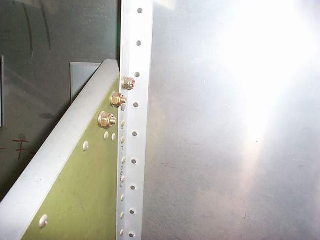
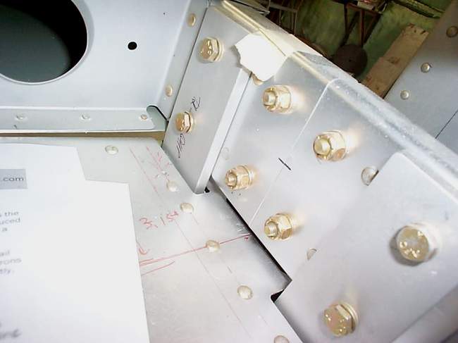
The upper longeron attachment to the firewall bracket uses flush fasteners (MS24694-S7 on the bottom weldment, and MS24694-S9 at the top weldment) through the fuselage side skin, the longeron and the steel bracket (This is a secondary attachment). There are also four #10 fasteners through the top of each longeron into the steel bracket (This is the primary attachment). On the HR2, the spacing for these fasteners are shown in the RV-4 plans. On the F-1, there is a page just to install these fasteners.
*end of comment*Q: On the HRII, do the F444 rudder/brake brackets get shortened to about 6" (compared to RV4)? Seems that it must be for them to fit between the top firewall angle and the firewall recess bend. You buys who have gone before, did you go ahead and mount those to the firewall before jigging it or wait 'til later? It appears that it would be easier on the bench!
A: Yes, the brackets are a little shorter, just make them fit. As for hanging the rudder pedals now, this will save lots of time later. You should clamp the firewall to the 404 bulkhead using those center two floor pieces. Those are the deep ones that run from the 404 to the firewall. They run back at an angle and to get the pedals to hang right and clear these pieces you should have them clamped in place when drilling the mounts for the pedals. After you have done this rivet the mounts to the firewall now, it is much easier on the bench. *end of comment*
Q: I'm just getting started putting together an HR2 fuselage, got the firewall nailed together, now can someone tell me what thickness do I use for the spacer between the firewall and the jig? The RV manual says to use 3/4", but when I do the math using HR drawings 101 and 146, I get 3-15/16". Is this right?
A: I believe I used the location of the F-404 BH to determine the firewall spacing aft of the jig. Assuming your jig horizontal members (bulkhead locations) are all in the right place, getting the firewall in the right place should be easy, just measure fwd from the F-404 bh location on the jig the distance given on John's plans. Even though the firewall is first on the jig, it's exact location is not important because of builder induced variances from jig to jig. The important thing is to have it positioned correctly in relation to the F-404 location. Hang the firewall, position the F-404, and then fine tune the location of the firewall. My firewall was just a couple of inches from the jig. *end of comment*
The comments about using the 404 bulkhead as a place to start are all right on. Another thing you might consider is to jig the engine mount to the firewall at the same time. This would mean moving the forward uprights even further forward. The advantage of doing this is there will be no doubt about your mount fitting later in construction. No shims or filing will be necessary. To mount the motor mount/firewall to the jig I used lengths of 3/8" threaded rod with lots of nuts. This allows you to move the firewall in and out in to facilitate the critical alignment to the fuselage. *end of comment*
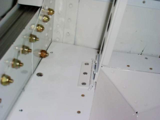
1) Mark and I had discussed the possibility that the small crossmember in the center of the #5 bulkhead could be attached (riveted) to front floor panel. This small angle is riveted (in my ship) to two small tabs on inboard side of the stringers. It must be removed for torque tube placement, then re-attached...probably by nutplates. I have accomplished the above and it seems to work well. I used existing holes after drilling rivets. This necessitated using single lug nutplate due to size of tab. It also means drilling #19 hole thru floor mount flange of front seat hinge. Once this is done the crossmember adds itself as an additional front floor panel stiffener and reinforces the front seat hinge. The addition of the hinge and front floor material also should add to its strength.
2) Front seat hinge-Mark also suggested removing two of the hinge segments from the center of the 12" front seat hinge and splitting the hinge pin. This is necessary since the hinge pin is too long to remove laterally. One could just split hinge pin in the middle and pull out the two halves laterally, but pins could vibrate out unless some mechanism to hold in place is attached, such as drilling and pin with cotter key. If the center segments are removed, then pins can be inserted from center and block any chance of accidental withdrawal.
3) I also decided to dimple and countersink two of the front floor panel rear edge attach screws on each side. These were the ones between the front seat hinge and the fuse sides that lie in the path of the passengers access to the rear foot wells and rudder pedals. This would make one less thing to catch on and even under carpet would make this area smoother. *end of comment*
Q: Does anyone have a good measurement for placing the bottom of the rear seat (i.e hinge)? Tom HallA: I measured the hinge line on my F1 and it is 5 and 5/8" forward of the 407 bulkhead. The RV-4 plans call this dimension as 4-1/4" from the hinge pin to the bulkhead. This measurement is taken from the rear floor line after it is trimmed even with the 407 bulkhead. You have to sort of build the seat back to fit the space and this hinge line worked for me, it is pretty close to what I have on my HRII. You have to have four pieces on the floor so that the center section of the floor can be removed. Two hinge pins are used. Tom Martin
*end of comment*Q: I can't find the length of the rear elevator push rod.
Do you have an exact length?
A: Start with 66 1/2" -- that will get you very close! I suggest you install only one
end until you see if the length fits your ship. Mark Frederick *end of comment*
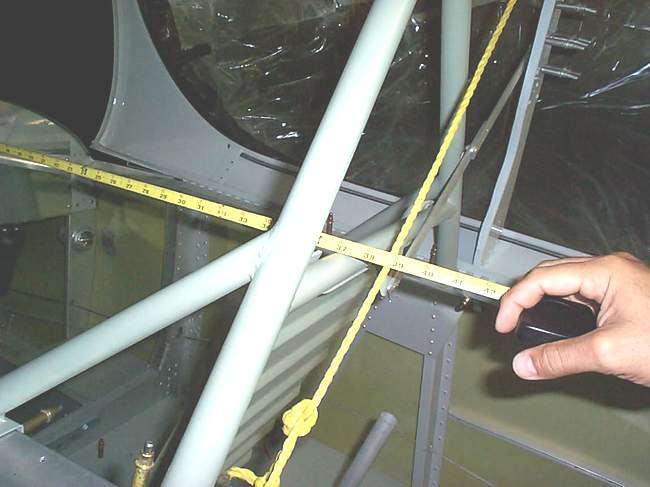
Bending fuselage longerons:
Clamp these pieces together, back to back. This makes them much easier to handle and match. I recommend clamping the cockpit area together, and bend the aft portion out to the correct dimension, and then the front portion. The bends are slight, the twist (at the fwd ends) is substantial. Bending tool: I use a 2X4 with a 1/8" x 5/8" deep saw kerf cut into it about 3" from the end, across the 4" face. Keep the tool about 3-4' long, for good leverage & control. The tough part is putting the "roll" into the front portion of the longeron (fwd of the #4 bulkhead). I found that I had to clamp the longeron in a vise, aft of the #4 attach point, and grab the front end with the 2x4, and twist the thing about 110-120 degrees to get the correct roll. Seems like a lot, but that's what it took! Recheck the bend after rolling -- it will probably change a bit. The longeron must fit the firewall weldments easily, and lay on the jig correctly. Put the bent longerons in the jig (with the firewall already jigged) & see how they fit. Mine usually fit right the first time! :-)Getting the width right at the #4 is important, also at the #7, and the #12. I use the factory measurement at the #7- 24.25 or so. John calls out 23.5, but I have always used the wider number. The rear seatback fits better with this measurement, but the canopy frame (flopper style) will need mods for this width. The slider is designed for this 24.25 width. I have occasionally found a slight twist in the longeron between #4 and #7, but this seems to pose no problems later. The longeron at #4 isn't truly flat, anyway.
Bulkhead #11
(both pcs) will have to be split to make it fit. I cut them ALMOST all the way thru, top to bottom, leaving a little bit at the bottom for alignment. I have also found that to get the rear fuse smooth, the front piece needs to be wider than the rear piece -- like it was a completely different part! This front piece will be split all the way down, into two pieces. Like the rear half, it will be rejoined with an .040 doubler, using the rivets that also hold the 411 bars in place. The 411 bars will mount between these two bulkhead halves, to facilitate riveting the flanges to the skin. Notch the lower longerons to fit the 411 bars after the fuse is straight in the jig.Bulkhead #12-
same as #11. However, don't split the back pc- make the front pc fit the back pc, and at the same time, make the assy fit the longeron angle/taper (again, keeping the longerons straight), and use an .040 doubler on the fwd side to put the halves together. When making this doubler, keep in mind how the tailwheel spring mount attaches here, and make the doubler wide enough to allow this, and keep the rivet pattern clear of the attach area. I put a c/s #10 screw thru the #12 bulkhead, flush on the aft side, to attach the rear flange of the spring mount to the #12 bulkhead. Put this screw approx. in the middle of the pattern of the three AN4 bolts that hold the v stab spar to the #12 and the spring mount. This screw won't be in the way later, so it is permanent.So, now we have the firewall mounted to the front of the jig. It's position is approximate at this time. The #12 bulkhead is also mounted at the aft end of the jig, and the longerons are clamped in place. At this point, only CLAMP your bulkheads to the longerons. If you have to reposition the firewall, the longerons will shift, too. This would twist all of the bulkheads that might be tack-riveted. Don't drill any bulkheads to the longerons until you are sure the fuse is as square/straight/plumb as you can get it.
Squaring up the firewall:
Getting the firewall on your airplane straight and plumb is very important. Spend as much time as you need to get this part RIGHT!At this point, you should have the firewall mounted upside down behind the forward fuse jig uprights. This assy should be level across the bottom flange measure off the 1/8" angle- it's more accurate), and plumb top to bottom, again across the 1/8" angles. This assy must be in the center of the jig, and be pointed EXACTLY at the tailpost. Level & plumb is easy- just adjust the 1/4" threaded rod that mounts the firewall assy to get this right. To get this assy to point at the tailpost is ... not so easy. Keep working at it.
Make 4 accurate marks on the top longerons on the 1/8"edge that is facing up. I make mine about 4" aft of the rear face of the firewall, just aft of the edge of the weldment ( again, measuring from the 1/8" angle where it touches the stainless metal) and 2" fwd of the EXACT measurement of the #4 bulkhead position. Make these marks like a "V", so you have a tiny point to measure to, but not a tiny mark to find. Measure across from the forward left mark, to the rear right mark. Then, measure from the forward right mark to the aft left mark. These measurements should be within 1/32". Distance of the two aft marks to the centerline should be exactly the same. If the longerons follow the centerline with equal side to side measurements to the tailpost, as measured at the bulkhead stations, then you can assume you have a straight fuselage, at least along the top longerons. Later, the bottom of the fuse will get the same treatment, only this time you will use the HRF 450 bars instead of the longerons.
Bulkhead #10:
Placement of this bulkhead is not critical, as the top half is mounted forward of the bottom half. Move the thing along the longerons until it fits good- just make sure the .040 skin will reach the flange for proper attachment. #7, #8 mount exactly as they do on the -4, same width dimension #(straight longeron, again) except for having no tops at this point. You can leave the tops on during jigging, but they will get in the way a bit. Builder choice. When you put the aft belly skin on, put two additional rows of .032 stiffener between #8 & #9, and a single pc between #9 & #10. This will keep oil-canning on landing to a minimum. You could pro-seal these in later, also.I've always thought that the center .063 longeron should run forward PAST the #7 bulkhead, up to the #6 bulkhead. This is a rather large area of un-stiffened skin, and I've seen some heat distortion in this area while parked on a hot ramp on my bird. I'll bet it flexes under G-loads, too. Make this longeron longer.
I'd like to see the joint at the #7 be a butt-joint. I have instructions, if you are interested. The joint at the #4 is an easy butt joint to make.
So, you've got the firewall in the jig, square with the centerline of your jig, and the #12 sits squarely on this line also, also vertically, like the firewall. The longerons are clamped SECURELY in place to the jig, and are straight where they are supposed to be, and are curved where they are supposed to be. The tail spring mount, with the spring inserted for eyeball alignment, is also clamped in place with the 11 and 12 bulkheads. This assy is aligned as per the plans, with the exception of the 11 being installed sort of backwards- the 411 bars are installed between the bulkhead halves. You have the 7, 8, &9 bulkheads sort of in place, held upright by the lower longerons & lots of clamps. Get the picture so far?
I think we ought to put in a cockpit, so we have some place to ride. Grab the #4 and stick it up about where you think it ought to be. Clamp the forward floor ribs to the firewall, and to the appropriate .063 angles you put on the forward face of the #4. Make sure the center of the #4 hangs exactly over the centerline of the longerons -- or in other words, make sure it is square. If this bulkhead leans to one side, you will not be able to square up this area of the fuse. It is possible to flute the #4 uprights just above the area where the spar attaches, and move them in a bit. Pay attention here, as there are pieces of channel that mount INSIDE the #4 uprights- make your flutes in the proper direction!
Now you get to fit & install the 450 bars -- these are the large 1/8" formed parts. This might take some time, as the 450 angles are not that easy to get to fit smoothly. You will need to form a twist in these parts -- they are sturdy parts -- be careful! The 450 angles have a top and bottom, also. The wider flange is the bottom, where there is a butt-joint between the side skin and the belly skin, making two rows of rivets necessary. Get them oriented correctly, and mark them BOTTOM FWD RT., etc., with an arrow, with a BIG PEN. You'll feel dumb if you screw them up like I did. John only laughs, and sends you more, for the proper fee, of course. These bars will need to be relieved 1/16" where they attach to the #4 bottom flange. Be sure to get a smooth transition here.
Firewall info:
The short 1x1x1/8" angle brace that attaches between the two 3/16" angle pads that attach the upper gear leg sockets to the firewall at the top fwd edge of the fwd floor ribs goes opposite on the Rocket from the -4 -- it attaches at the bottom of these two angle pcs, not at the top as shown on the -4 drawings. Use 4 ea. AN3 bolts here -- we've got some LONG legs sticking out there, putting a LOT of force in this area. To make this pc, I used the 450 angle mat'l that comes with the -4 kit. It can't be used for much else (rudder stops also), as it is opened up a bit. I also use a pc of this angle to brace the two inner rudder pedal mounts to each other- they normally only fasten to the .016 stainless that makes up the firewall. This firms these parts up considerably.So, now you've got the fwd area of the fuse square & plumb, and the #4 bulkhead is clamped in place, not forgetting the proper angle of incidence. The rear fuse bulkheads, from the 7 to the 12 bulkhead should be clamped in place, also. Clamp some .063 longeron material to the rear bulkheads, so they don't fall on your head.
Fwd floor ribs:
These parts go into the Rocket just like the RV-4 with the same fastener callout, and spacing. The .063 angle that supports the fwd .040 floor pieces (attaches to the outside of the floor ribs, fwd of the spar) should match the height of the .063 pieces already mounted to the #4 bulkhead, at whatever dimension you put them. The 402A piece that fits in between the floor ribs has given me some trouble in the past. I think the sides of this piece are not really parallel. So, I attach .032 angle to the inside of the floor ribs at the appropriate station, and cut the flanges off of the #2 center piece, and attach it to the angle. You could put another angle piece on the outside of the rib, and attach the #2 uprights to those. Sometimes the #2 uprights will fit, but I've usually had to malletize them a bit.Seat ribs:
the fuse is stretched (4" total) aft of the rear spar carry-thru, fwd of the rear seat bulkhead. John sends you the new ribs for this area, and they fit pretty good. Adapt the std -4 drawings to the Rocket dimensions, and you'll be fine. I do change the #5 bulkhead a bit. I rivet the two small pieces that help make up the center of this bulkhead to the seat ribs, and make the center 8" pc of .063 removable. I put nutplates on the two small pieces of angle to keep the center piece of angle removable (to be able to put the torque tube in & out) . This is easier than fussing with the AN3 bolts the would normally hold the two small pieces to the seat ribs- these are hard to get at. I use the formed part of the -4 spar carrythru to make up the seatbelt anchors for the front seat- it's already bent with the proper offset. Make up two flat pieces of .063 to complete the belt attach point. IMPORTANT!! These fwd lap belt anchors mount at 35 deg -- NOT 30 deg as shown in the -4 plans.When you make the cutout in the fwd seat ribs for the aileron pushtube, make the hole in the outer rib somewhat higher than you would think- not in the center of the stiffener ring, but towards the top. You will actually remove part of the ring at the top to get clearance in service. The inner seat ribs will need a cutout for the spar splice plates. Make this cutout big enough so that you can actually get the parts in! VERY IMPORTANT: Get the distance between the front & rear spar attach points correct! Match this dimension to your wings.
You should now have a thing that closely resembles a fuse skeleton in front of you. Congratulations! Remember how you squared up the fwd fuse area by "X" measuring? Square up the cockpit area the same way. Take your measurements for your squaring marks from the firewall and from the center of the bulkheads. Watch the centerline string (between the firewall & #12), and keep it in the center! Once you get everything squared up, with the string running down the center, firewall to tailpost, you can drill & clecoe the bulkheads & ribs in place, back to the #7.
The height measurement from the longeron to the outer corner of the #7 is 22.75" Aft of the #7, vertical alignment becomes an issue, as the belly skin should lay smoothly on these bulkheads. Your eye, sighting from the #12 fwd to the #7, will be able to see any variation here. You may need to trim the flanges where they lay on the top longeron to adjust the bulkhead height as needed. Once you get the skeleton built, put in or at least fit everything you can before skinning. It's a LOT easier to do some of this stuff now- (floors, nutplates, controls, wiring holes, rear seat belt attach brackets, rear seat shoulder harness mounts [use the RV-6 parts here], etc.)
Skinning: Builder input will help here. Send your experiences. *end of comment*
Return to the homepage: http://www.vincesrocket.com/
Last updated: 09/01/06
CAUTION: This web site is not a publication of, nor approved by, Harmon LLC, Team Rocket, Van's Aircraft or any other person or entity listed herein, except me. Be advised that I am a blithering idiot with neither brains nor money and my advice is not to be trusted. So there. You have been warned! Vince