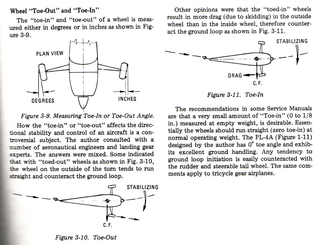
 The pertinent info straight from Ladislao Pazmany himself.
Gear alignment: Toe-in versus toe-out
I have done more than just a little research and been in more than just a few "discussions" with other builders over whether toe-in or toe-out is the proper set up for our planes. I finally sent an email to Ladislao Pazmany, designer of many successful lightplanes and the author of Landing Gear Design For Light Aircraft. If anyone can answer this question it would be Paz. Here's the unedited correspondence:
Dear Mr. Pazmany:
For a conventional gear lightplane with tapered rod spring main gear,
should the main wheels have any toe-in or toe-out?
Vince
Dear Vince:
Unfortunately your question doesn't have a straight answer. There is a
big controversy on the subject. Please review the attached document
in order to understand it better. (the attached document was scanned from
my book Landing Gear Design For Light Aircraft )
Regards Paz
The pertinent info straight from Ladislao Pazmany himself.
You decide.
Landing gear, wheels, tailwheel, and brake system.
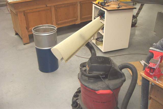
Maintaining tire pressure: If you haven't a system for servicing your tire pressure without pulling the wheel pants, here is a tip. I have used it on all my airplanes, and boy does it save time. With a hole cutter I put a 1'' hole right over the valve stem of the tire. As I remember that is 1 7/8'' out from the axle centerline (check the measurement before cutting).
Wicks sells a Tinnerman Patch Plate that perfectly covers the 1'' hole and is already primed for paint. You never notice the thing when its painted along with your wheel pants. Wick's number is (800) 221-9425, and the part number is P/N: A6914-1024-1. You of course will need two, and they cost $3.50 each.
Wick's approves them for patching bullet holes in aluminum aircraft skin, which comes in useful for me sometimes. Jim Cash
NAPA sells a valve stem extension that I carry along with me in my tool bag. I believe Cleaveland tool also sells a similar extension. They're about 6" long; all you have to do is pop the cover as Jim mentions, move the airplane until you can see the stem, screw the extension in, and fill up the tires, check pressure, etc. When your done you remove the extension, pop the cap back in and go fly. Bob
And if you paint a small indiscrete line on the inside of your tires where the valve stem is located, you can roll the plane until the mark is on the bottom of the tire and you won't have to keep checking to see if the stem is lined up with the hole in the wheel pant (assuming your access hole is directly below the axle). Ivan Haecker #65
Well, everyone else had a comment and I do too. Someone said to "throw the valve cap away." Don't to that since dirt could get in the valve. Do this:
Find a piece of rubber hose or Tygon tubing that will wedge over the valve stem cap. Now find a dowel rod or similar metal rod that will wedge into the tubing.
Use the rod with the tubing on the end to EASILY reach through the hole in your wheelpant to remove and replace the valve cap.
I don't know about the Tinnerman patch plate for $5 each. Around here we all use the snap-in hole plugs, p/n SHP100, for $0.46 each. Much cheaper and you don't need a screwdriver or long, skinny fingers. Vince *end of comment*
A lesson learned from my RV-6, you want to install your wheelpants with enough clearance so that a flat tire doesn't result in the total destruction of your wheelpant and possibly the gear leg fairing. I know those tight and low pants look slick and help your top speed by about 1/2 knot, but if your tire goes flat you want to leave yourself enough room to stand on the rim without ripping the pant off.
That will also give you some options too on where to land. You know you're going to want to take your Rocket into some grass strips and such. Heck, when you land at AirVenture and you're asked to taxi in the grass between 18-36 and the taxiway, you don't want to embarrass yourself in front of the airshow crowd by stopping and picking up your wheelpants and throwing them into the rear seat! Randy #95 *end of comment*
Brakes:
Q: What size are the hoses for high pressure brake line. (Steel Braided?)
A: -4 size here, straight ends. Hose cut lengths can vary, but I use a 10" length of hose on the brake line near the caliper, and you will have to determine the length for the master cylinder-to-bulkhead fitting on your installation. Mark Frederick *end of comment*
On this Rocket I tried to do the piston down installation. I went to a lot of work to modify the pedal so that there was adequate clearance and yet when I finally got around to mounting it I just was not happy with the room. I gave up on the idea and mounted the cylinders up. The downside is that you will probably have to undo the bottom bolt and pull the cylinder up to bleed it. Once done, you bolt it down and forget it. Both my RV4 and my rocket had the cylinder up, I now ask myself why I spent any time changing something that worked OK??? Tom Martin *end of comment*
Bleeding brake cylinders--- Cylinder up or down is much more of an "idealistic" problem than it is an actual one, whatever works easiest is the way to go. The cylinders will work just fine either way. However, this problem brought back memories of past problems that I had, referring to actually bleeding the brakes. The "standard" way is to fill your reservoirs, then pump the brakes, holding the pressure while simultaneously bleeding pressure from the bleed valve on the brake cylinder, close the valve, pump the brakes again, then rebleed---until all air is purged from the line. A rather long, and somewhat complicated procedure that is totally negated if you allow the reservoir to get low enough that you accidentally "pump in" some more air. (Don't ask me how I know that!) A much more efficient way is to use a standard pump-type oil can with a long, flexible hose that will attach to the bleed valve stem. With the hose disconnected and the (clean) oil can filled with hydraulic fluid, pump the can until the hose is completely filled. Then open the brake cylinder bleed valve about a half-turn, and attach the hose from the oil can. Gently pumping the oil can will fill the brake cylinder and line from the bottom, and accomplish line bleeding from a much more effective and easy direction, (bottom up), also filling your brake reservoir in the process. Of course, you have the reservoir fill cap removed, to let excess air escape, and this port is watched to determine when the reservoir is full. When the oil overflows out of the reservoir, then the system is completely purged, and the oil reservoir full. Close the purge valve, and disconnect the oil can hose. NOW COMES THE HARD-LEARNED LESSON! AT this point there is TOO MUCH oil in the system, there is no reservoir air space for any return or release of the brakes! AND, since you were purging the system via pressure, the brake cylinders are probably all the way out. What this means is that the brakes possibly can not fully release, and you will have dragging brakes. (Makes the plane pure hell to move around by hand! Again, don't ask me how I know that.) Very simple solution--depress the brake pedal, and while you hold the pressure, your partner lightly cracks the bleed valve on the cylinder until enough brake fluid is drained so that one stroke of approximately 1/2-3/4pedal travel drain-down is accomplished. Retighten the bleed valve, and there will now be enough reserve air space in the reservoir to allow the brakes to fully release. Now reapply the reservoir fill cap, and you are done. *end of comment*
I put together some instructions on how to modify and use the bleeder. The bleeder bottle is a "R L Flowmaster Home And Garden Sprayer Home & Garden Sprayer Model 1998.
Before this bottle will work for bleeding brakes you'll need to modify it. Take off just the very end of the nozzle (part with the spray orifice in it) and from the outside carefully drill it out to 1/4". I found a Unibit worked quite well, just go real slow so it doesn't grab. Cut a two foot piece of 1/4" O.D. X 1/8" I.D. clear poly (vinyl) tube. Cut a piece of 3/16" O.D. Nyla Seal tube exactly .625 (5/8") long. Make sure all the ends are cut square, other wise the connection will leak. Slide the nozzle piece, that you previously drilled, over the 1/4" tube about 2", make sure the threaded end is towards the 2" side. Heat the 2" end of the 1/4" tube in a cup of boiled water for about 3 minutes. This will soften it and allow the .625" piece of Nyla Flow to be inserted into it easily. Be sure to quickly push the Nyla Flow all the way into the Ploy tube so the ends are flush, you must do this before poly tube has a chance to heat up the Nyla Flow piece.
Let this assembly cool for ten minutes, and then, insert it into nozzle holder and tighten the nozzle nut. That's it, your ready to bleed brakes. Helpful hint, use a 1/8" rivet to plug the poly tube when not in use. Here is the procedure I use to use the Bleeder.
Fill the tank with fluid. Pump up the pressure ( you don't need much). Press on the discharge button until the fluid fills up the clear poly tube. Stop pressing on the button and slide the end of the poly hose onto the bleeder fitting on the bottom of the caliper. Open the bleeder fitting then press on the discharge button until the fluid reservoir is about 1/4 full, then stop filling. Some times the check valves in the brake cylinders stick and it is necessary to pump lightly once or twice to free them so that the fluid will start flowing.
It is much easier if you have someone with a flashlight look into the reservoir and tell you when to stop. Stop filling at about 1/4 full. Tighten the bleeder nut and move to the other side. This is were the 1/8" rivet comes in handy. Repeat, but this time let the fluid fill to about 3/4 full.
Check pedal pressure, it should be quite hard, and check for leaks. That's it. Garry LeGare *end of comment*
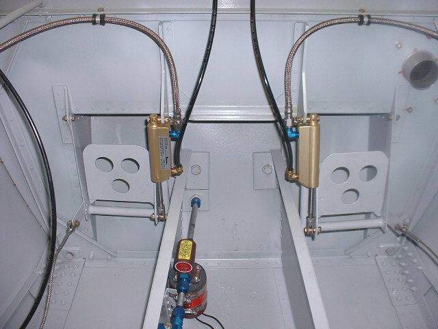 This is my brake installation. It is pretty much standard RV4 except for the use
of braided line on the pressure side. It is not possible to see from this
picture but the castle nuts are held with safety wire not cotter pins. This is a
service bulletin that Van put out years ago as the cotter pins were being broken
off by shoes, the bolts could then fall out leaving you with no brake and or
rudder. For those of you having problems with these types of issues I highly
recommend purchasing a set of RV4 plans, a lot of little details are there.
(The older RV-4 plans have MUCH more detail than the new sets. Get a
1980's set if you can find 'em. Vince) Tom Martin *end of comment*
This is my brake installation. It is pretty much standard RV4 except for the use
of braided line on the pressure side. It is not possible to see from this
picture but the castle nuts are held with safety wire not cotter pins. This is a
service bulletin that Van put out years ago as the cotter pins were being broken
off by shoes, the bolts could then fall out leaving you with no brake and or
rudder. For those of you having problems with these types of issues I highly
recommend purchasing a set of RV4 plans, a lot of little details are there.
(The older RV-4 plans have MUCH more detail than the new sets. Get a
1980's set if you can find 'em. Vince) Tom Martin *end of comment*
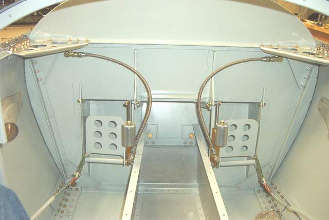 My brake installation, using the ACS reservoirs.
 CHANGED
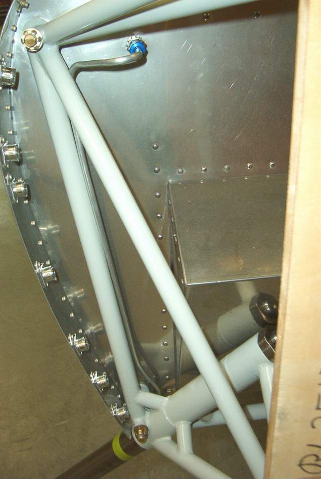
The brake line runs down the engine mount and exits behind the gear leg.
CHANGED
The brake line runs down the engine mount and exits behind the gear leg.

 CHANGED A loop of aluminum at the caliper to flex a bit. Gotta be careful not to
kink the line during future brake pad changes. As you can see, I'm
using the Cleveland brakes.
CHANGED A loop of aluminum at the caliper to flex a bit. Gotta be careful not to
kink the line during future brake pad changes. As you can see, I'm
using the Cleveland brakes.
That solid line is OK, but I replaced it with teflon/ss lines after hearing Jim Winings tales of solid lines breaking. DOH!
An easy way to fill the brakes with fluid is to get a large (50cc or bigger) syringe and use it to fill the system from the bleeder valve.
12-01-03: We were talking about brake lines a few days ago. I had concerns. I hate when my airplane won't stop. I had planned to use solid aluminum tubing from the firewall to the caliper as is done on other RVs, etc. I've never been wild about the Nylaseal stuff due to heat softening concerns so I didn't want to use it.
Then Jim Winings and Mark convinced me to take a look at using something other than solid aluminum lines. They explained to me that the world would end, the sky would fall, etc, and my brake lines would break... blah, blah, blah :-) Seriously though, I value their opinions and the change I'm gonna make is easy and cheap.
Here's what I found. Maybe this will cause others to rip out their finished brake lines and set themselves back a week. LOL
Aeroquip makes a teflon lined S/S hose, FC807-4, that is equivalent to their teflon lined S/S brake (racing) hose. They told me so on the phone, although they really can't say that. The difference is that FC807-4 is $1.20/ft and the racing hose is $4/ft. They use the same fittings.
http://aeroquip.murdockindustrial.com/hoseselector.htm One supplier in Ohio. The kid was quite helpful.
https://fluidpower.eaton.com/intradoc/groups/public/documents/prod_bulletins/ja886.pdf Specs for the hose. In a nutshell, -100 to 450 degrees, operating pressure 3000 psi, and burst at 12,000 psi. 0.06 pounds per ft
I bought enough line to and fittings to make every part of the brake line, both sides, and it was only about $70. Cheap. And the fittings are easy to install and reusable.
 I threw the solid aluminum line away
and installed the nice teflon/ss that you see here. You can see pictures
of the caliper end below in the gear leg fairing section.
I threw the solid aluminum line away
and installed the nice teflon/ss that you see here. You can see pictures
of the caliper end below in the gear leg fairing section.
I'll probably use this same hose elsewhere under the cowling for oil and fuel lines. For gosh sakes, somebody tell me now if this is a bad idea. (TOO LATE NOW!) Vince *end of comment*
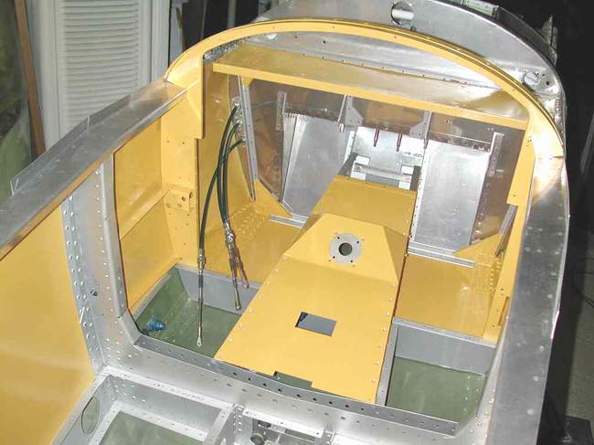
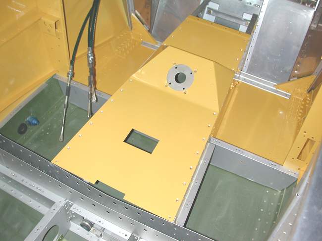
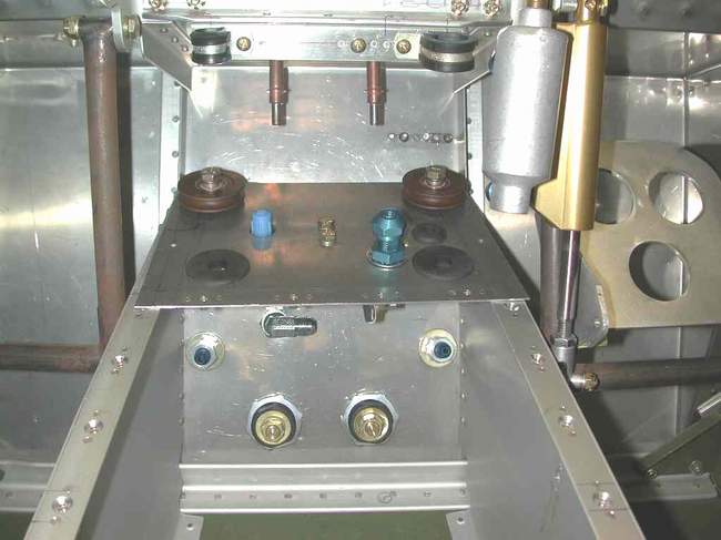
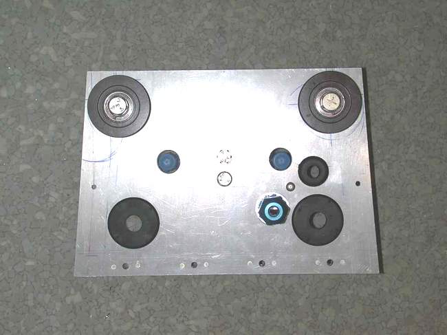

I installed the Cleveland unit, P/N CWB60-5 from the Wicks catalog. I mounted it to the underside of a short (6") piece of aluminum that covers the forward section of the "dog house" center console. See the attached pictures. I purchased a push/pull cable with button release to control the valve. This piece is permanently pop riveted to the forward dog house and the original dog house cover is shortened, joggled and screwed to the forward piece for easy removal during inspection and repair. Two braided lines will connect the master cylinders to the fittings that poke through the top of the plate and two more hoses connect the brake valve to the firewall bulkhead fittings mounted low in the dog house area (see photos). The other holes in the forward plate are for wiring and there are a couple of pulleys that I will use to close the loop on the rudder pedal system. Slack rudder cables are just a pet peeve of mine. As Mark would say, clear as mud. Let me know if this is not clear and I will try to explain further or get more pictures. Call if you need to at (619)980-8348. Scot Stambaugh *end of comment*
Jacking the airplane up: Mark gave me the solution a couple of years ago and it works. Simply place a radiator clamp (or muffler clamp) around the gear leg as low as you can get it, and turn it so the bolt portion is on the bottom. This gives a very good protrusion (and at the right angle) to slip a small floor jack under, and it lifts just as Tom's modification does. To make sure it didn't slip, I placed two clamps one above the other, and it has worked well for two years. At the rate I was going thru tires and brakes (another story) before the shims, this system was exercised quite often. Jim Cash *end of comment*
Gear leg / axle sockets
/ wheel pant support:
There used to be a section on gear leg problems here. I moved that section to the bottom of this page since much of it is ancient history now. Vince
2/1/2003 update:
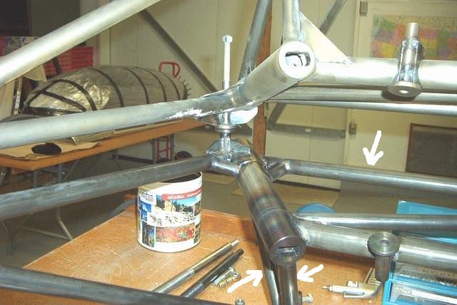
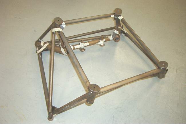
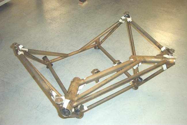
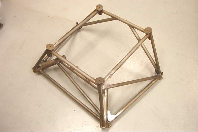
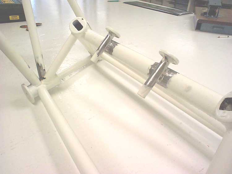
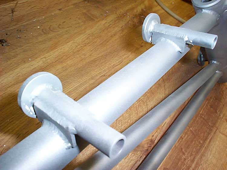
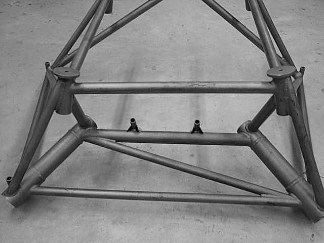
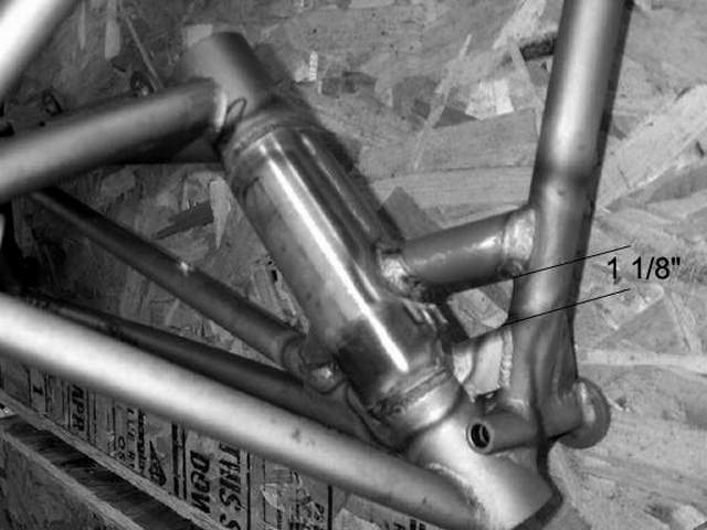
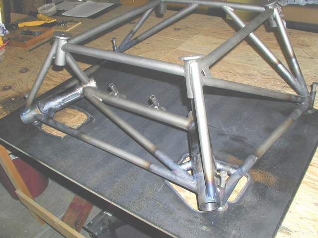
For what it's worth, even though I have a nicely gusseted Mk 1 mount, I have the 3rd Indy mount to roll off the assembly line. I agree with Jim, it's nice to have a backup available, although my backup will be the gusseted Mk 1 mount. I plan to use the Indy mount barring more unforeseen problems.I visited Jim Winings and Bob Japundza on 2/1/03 and picked up my new Indy mount. It is a work of art. I am quite impressed with the workmanship and the thought that went into this mount. You can see it in the photos below. The old Mk 1 with gussets is on top of the Indy mount. As is obvious in the pictures below, the socket is substantially thicker, the tubing size is increased in several areas as shown in the first picture by the white arrows, the tubes that the firewall bolts go through are twice as thick, and the upper corner weld clusters are no longer cantilevered out from the firewall but are right next to it. Also the gussets that support the bolt tubes in the lower corners are 0.1" thick.
Jim Winings also explained that the engine mount pads, the ones that actually touch the rubber Lord mount donuts, were adjusted slightly on the new mount to eliminate a built in need for additional unnecessary washers. Hard to explain in text but easy to see in person. Vince *end of comment*
 If the Indy mount doesn't work, I've got my own design shown here. LOL! Vince *end of comment*
2/10/2003 update: Installation of my new Indy mount was complicated by the fact that I had already drilled the firewall holes to match the old Mk 1 mount. As with any welded assembly, the holes in the new mount were off slightly due to warpage from welding. I had three problems to fix: 1) the top bolt tube holes were too close together due to warpage. 2)the bottom bolt tubes were warped inward about 1/16" at the firewall and were not perpendicular to the firewall like they should be. They had to be made to fit flush with the firewall. 3) the Indy EM bolt holes didn't line up with the firewall holes. See the pics below to see what I did to fix the problems.
Problem 1) Sorry no picture. The top bolt tube holes were too close together. I stuck the EM under my International 460 tractor. Next I put a hydraulic jack on top of the top tube between the Lord mount ears. I raised the jack against the tractor until the top tube was straightened and the welding warpage was no more. I went slow, raised and lowered the jack several times so I didn't over bend anything. I could have used a press for this job but that would have required that I drive to my buddy's house. The jack and tractor worked fine and took 1/10 the time.
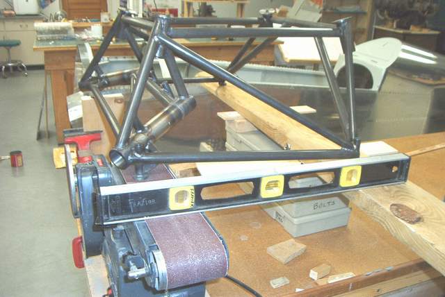 Problem 2) The bottom bolt tube pads don't fit flush against the firewall.
The pads on the bolt tubes were more than thick enough to grind away the 1/16"
from one edge necessary to obtain a flush fit with the firewall. Since all
four corner bolt tube pads should lie in the same plane, I set up my belt sander
to grind away the excess metal. I leveled the plane of the belt sander.
Then I used boxes, block, etc to jig the four corners of the EM to sit
perfectly level with the belt sander, sort of a poor man's surface grinder
setup. Next I turned on the belt sander and ground off the lower left bolt
tube pad until it was flat on the belt. A mirror image setup was
required to grind the other lower bolt tube pad.
Problem 2) The bottom bolt tube pads don't fit flush against the firewall.
The pads on the bolt tubes were more than thick enough to grind away the 1/16"
from one edge necessary to obtain a flush fit with the firewall. Since all
four corner bolt tube pads should lie in the same plane, I set up my belt sander
to grind away the excess metal. I leveled the plane of the belt sander.
Then I used boxes, block, etc to jig the four corners of the EM to sit
perfectly level with the belt sander, sort of a poor man's surface grinder
setup. Next I turned on the belt sander and ground off the lower left bolt
tube pad until it was flat on the belt. A mirror image setup was
required to grind the other lower bolt tube pad.
 When done with the sanding, I used a straight edge to check that all four
corners were in the same plane. They were! Woo hoo.... it worked.
And worked great. When I held the EM up to the firewall the four corners
were all flush and straight with the firewall... as they should be.
When done with the sanding, I used a straight edge to check that all four
corners were in the same plane. They were! Woo hoo.... it worked.
And worked great. When I held the EM up to the firewall the four corners
were all flush and straight with the firewall... as they should be.
 Problem 3) The Indy EM bolt holes didn't line up with the firewall holes.
I needed to move the existing firewall holes a bit. Oh joy! Moving
holes isn't possible. However, enlarging holes is possible. After
some careful measurements of the EM bolt tubes, I determined that it would be
possible to use AN7 (7/16") hardware instead of the usual AN6 (3/8") hardware.
The bolt tubes on the Indy mount are MUCH thicker than those on the MK 1 mounts
and my measurements showed that I would still have over 50% more wall thickness
remaining after enlarging to the AN7 size compared to the Mk 1 EM wall
thickness.
Problem 3) The Indy EM bolt holes didn't line up with the firewall holes.
I needed to move the existing firewall holes a bit. Oh joy! Moving
holes isn't possible. However, enlarging holes is possible. After
some careful measurements of the EM bolt tubes, I determined that it would be
possible to use AN7 (7/16") hardware instead of the usual AN6 (3/8") hardware.
The bolt tubes on the Indy mount are MUCH thicker than those on the MK 1 mounts
and my measurements showed that I would still have over 50% more wall thickness
remaining after enlarging to the AN7 size compared to the Mk 1 EM wall
thickness.
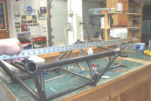
Here's the wall thickness differences of the bolt tubes for those who worry
about these things:
Mk1 mount: 0.500" OD, 0.375" ID, which gives approximately 0.063" wall
thickness.
Indy mount: 0.625" OD, 0.375" ID, which gives approximately 0.125" wall
thickness. After drilling the tube to accept AN7 hardware, the wall
thickness is approximately 0.094"
I held the EM up to the firewall and made careful guestimations of where I could "egg" out the existing firewall holes to best fit the new mount. I hoped that if I was careful, everything would turn out perfect. However, I was mentally prepared to remove the weldments behind the firewall and weld the holes closed if my plan didn't work.
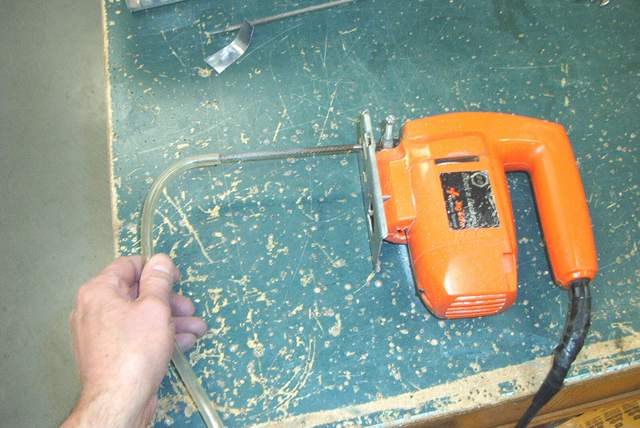
I used the "finger breaker" shown above to egg out the firewall holes where needed. It's a jig saw with a round file chucked in it. The tygon tubing on the business end of the file allows you to hold it while it's running and apply pressure in the direction you want to egg the hole. It took about one minute to file the holes. If I'd done it by hand it would have taken me an hour.
After I guesstimated the new egg shape of the holes, I put the EM back against the firewall and used threaded rod to bolt it firmly in position. It looked pretty good. I had high hopes that the small amount of egg shape I'd made to each hole would be cut away when I ran the 7/16" reamer through the holes.
 The shank of a 7/16" reamer is 3/8". That is perfect for this job.
I'm no machinist, but I think it's MUCH easier to keep that reamer aligned if
you pull it through the hole. This allows the shank to keep everything
aligned with the 3/8" bolt tube hole. Use plenty of cutting oil and clean
out the chips frequently.
The shank of a 7/16" reamer is 3/8". That is perfect for this job.
I'm no machinist, but I think it's MUCH easier to keep that reamer aligned if
you pull it through the hole. This allows the shank to keep everything
aligned with the 3/8" bolt tube hole. Use plenty of cutting oil and clean
out the chips frequently.
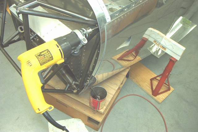
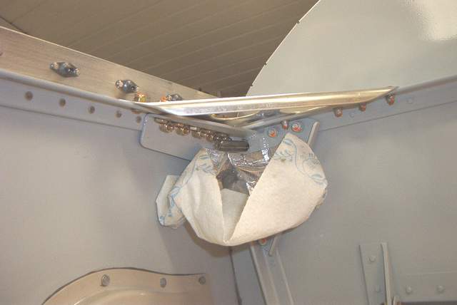 Here's a dribble diaper I put in place to keep 99% of the mess off of my
interior.
Here's a dribble diaper I put in place to keep 99% of the mess off of my
interior.
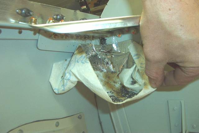 Here's the diaper after reaming. Yuck. All that oily stuff would
have been on my floorboards.
Here's the diaper after reaming. Yuck. All that oily stuff would
have been on my floorboards.
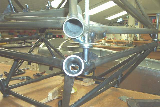
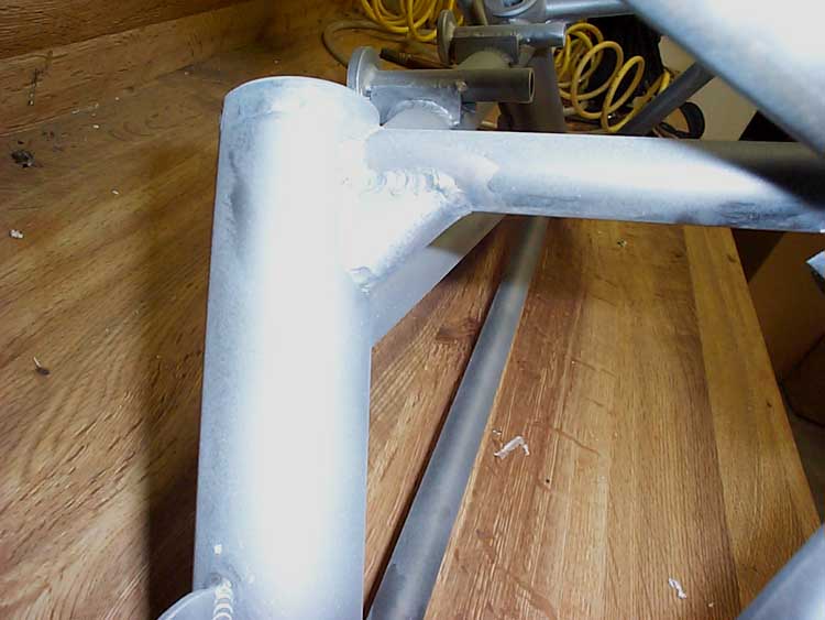
 This is the Indy mount after reaming the four corners to 7/16". "IT WORKED!!!" All four corners
turned out perfectly round and the bolts dropped right in with hand pressure.
Also when I tightened the lower bolts they seemed to tighten perpendicular to
the firewall as they should. I was a bit concerned that they would be
slightly tipped, but the reaming process ate up any misalignment that had been
present.
This is the Indy mount after reaming the four corners to 7/16". "IT WORKED!!!" All four corners
turned out perfectly round and the bolts dropped right in with hand pressure.
Also when I tightened the lower bolts they seemed to tighten perpendicular to
the firewall as they should. I was a bit concerned that they would be
slightly tipped, but the reaming process ate up any misalignment that had been
present.
I still need to finish the center bolt holes. I think I can ream one as it is. The right side hole will probably require a new aluminum angle behind the firewall, but that shouldn't be a big deal. (Famous last words.)
I talked to Mark about the center holes the next day. As stated above, the holes in the aluminum pads behind the firewall were slightly egg shaped after the reaming operation. Mark said to put JBWeld in them and re-ream to fix. He claims that a minor egg shape of the holes is no big deal anyway. The JBWeld will fill the hole and the nuts, bolts, and washers will hold everything together just fine. I agree.
WOO HOOO! I'm not out of the dark yet, but I can see light at the end of the EM tunnel! Vince *end of comment*
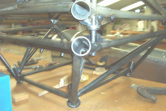
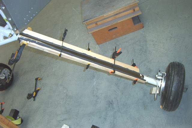
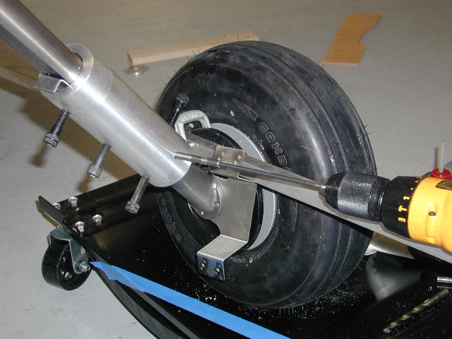
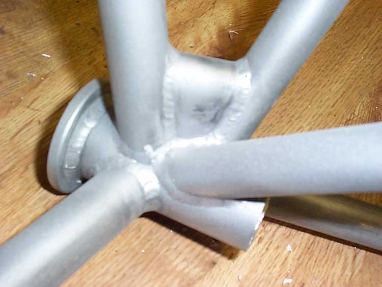
3-3-03: Getting the gear leg and axle socket drilled. Let's go straight to the pictures.
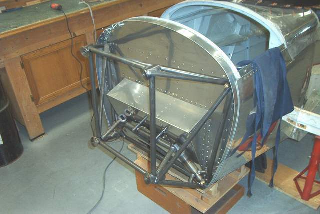
 First we get the EM perfectly level. I shimmed the 4 corners until the
shims were level then clamped the EM down on top of them. This should
simulate the firewall for plumbness except it's rotated 90 degrees. Make
sense?
First we get the EM perfectly level. I shimmed the 4 corners until the
shims were level then clamped the EM down on top of them. This should
simulate the firewall for plumbness except it's rotated 90 degrees. Make
sense?
 The technique that Mark shows in his manual for using a visegrip to hold the
axle socket didn't seem to work very well. I always moved the socket when
I squeezed the visegrip and it didn't hold very well. Not good when you're
about to drill a hole in an $850 stick of titanium.
The technique that Mark shows in his manual for using a visegrip to hold the
axle socket didn't seem to work very well. I always moved the socket when
I squeezed the visegrip and it didn't hold very well. Not good when you're
about to drill a hole in an $850 stick of titanium.
I had an epiphany (it happens) and decided to install a set screw. Drill and tap for a 6-32 set screw 1/2" from the top of the axle socket. This will hold everything FIRMLY in place on the gear leg. IT WORKS GREAT!!! Don't risk your expensive gear legs by using that sloppy visegrip technique.
Mark was concerned about the set screw making a scratch on the titanium, but the mark it leaves is tiny and easily polished off. As an option you could put the set screw at the bottom end of the gear leg where scratches are no worry, although Mark claims that the bottom of the socket is more highly loaded and to avoid putting a hole there. OTOH, it seems to me that the weakest spot of the axle/axle socket area is the four 1/4" bolts holding the wheel on, not a tiny set screw hole anywhere in the axle socket.

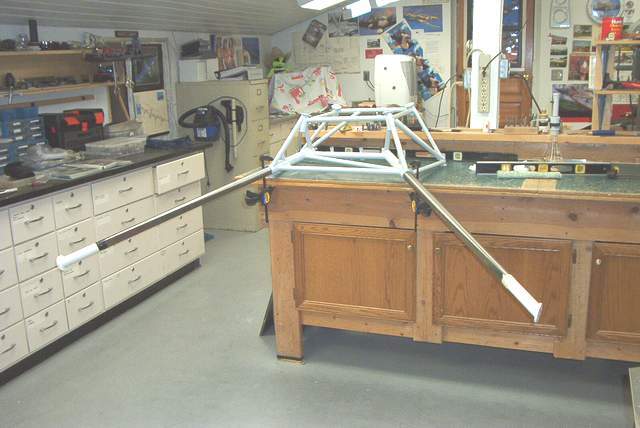
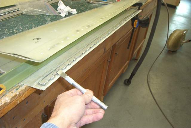
 I used a straight length of 6061angle about 27" long instead of a board.
27" is
twice the length of the board shown in the F-1 manual. This allowed me to tape a
1/16" drill bit to the top of the angle where it holds the thread away from
the angle. The drill bit provides the proper angle
for the plumb bob thread when the thread just touches the lower end of the
angle. Then simply tighten the set screw. Easy.
I used a straight length of 6061angle about 27" long instead of a board.
27" is
twice the length of the board shown in the F-1 manual. This allowed me to tape a
1/16" drill bit to the top of the angle where it holds the thread away from
the angle. The drill bit provides the proper angle
for the plumb bob thread when the thread just touches the lower end of the
angle. Then simply tighten the set screw. Easy.
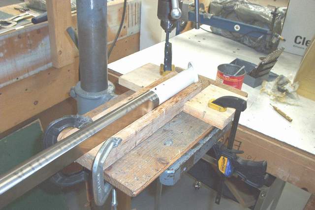 Then move the leg to the vee block that was waiting on the drill press and drill
with lots of oil 1/8", 3/16", 1/4", 19/64", ream to 5/16".
Also easy.
Then move the leg to the vee block that was waiting on the drill press and drill
with lots of oil 1/8", 3/16", 1/4", 19/64", ream to 5/16".
Also easy.
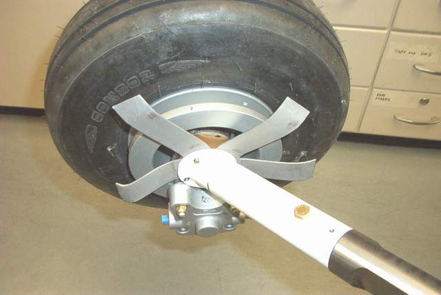
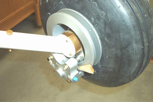 This is a picture of a set of Cleveland brakes. The brake is
oriented behind the axle, not on the bottom as it appears in this picture.
The picture was taken while the EM was clamped to my workbench, 90 degrees from
how it would mount on the plane. See the picture below if this is
confusing.
This is a picture of a set of Cleveland brakes. The brake is
oriented behind the axle, not on the bottom as it appears in this picture.
The picture was taken while the EM was clamped to my workbench, 90 degrees from
how it would mount on the plane. See the picture below if this is
confusing.
It took me a couple of minutes to figure out that the brake flange slid over the axle. I tried to mount it between the axle and gear leg... DOH! It looks like it will work there, but when you look closer you realize that only one pad will bite on the disc. That wooden wedge keeps the wheel from turning while I'm mocking up the wheel pant cutouts.
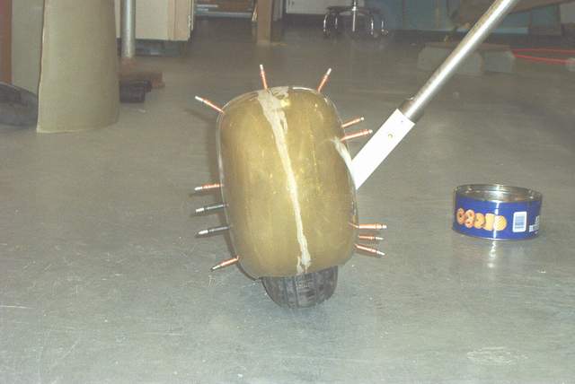
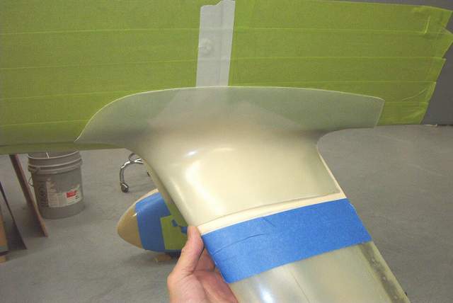
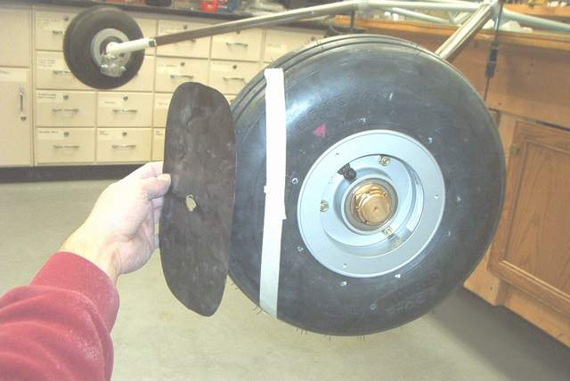 Wagging a template to make the initial wheel pant cutouts.
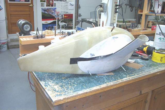
 Untrimmed Sam James wheelpants.
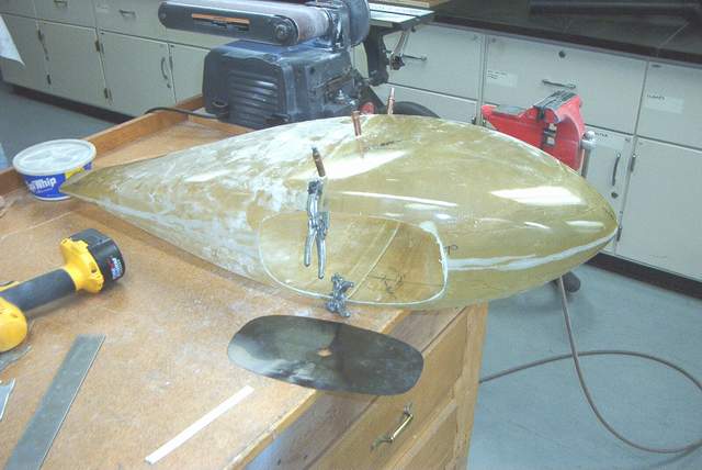
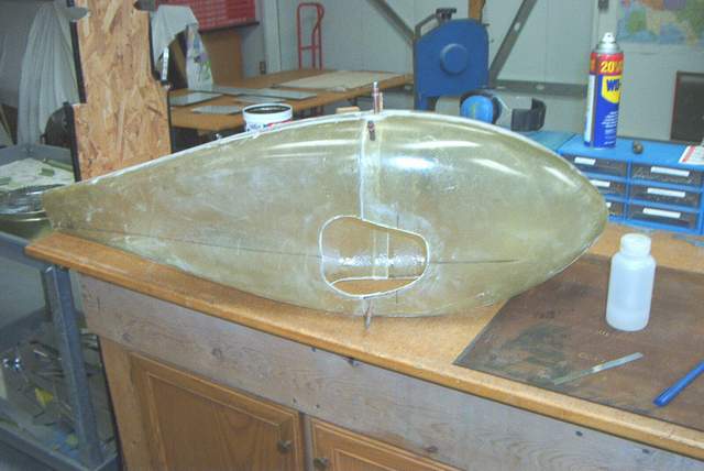 Making the initial cuts. I used a jigsaw because my chain saw was out of
gas. It makes a fast but somewhat rough cut. I'll clean that up
later.
Making the initial cuts. I used a jigsaw because my chain saw was out of
gas. It makes a fast but somewhat rough cut. I'll clean that up
later.
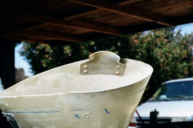
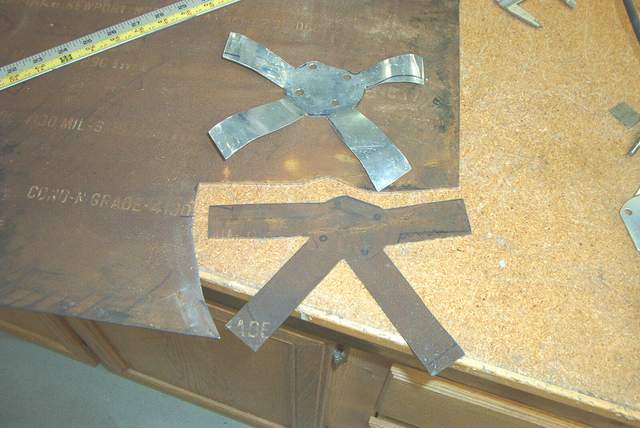
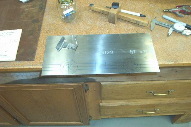
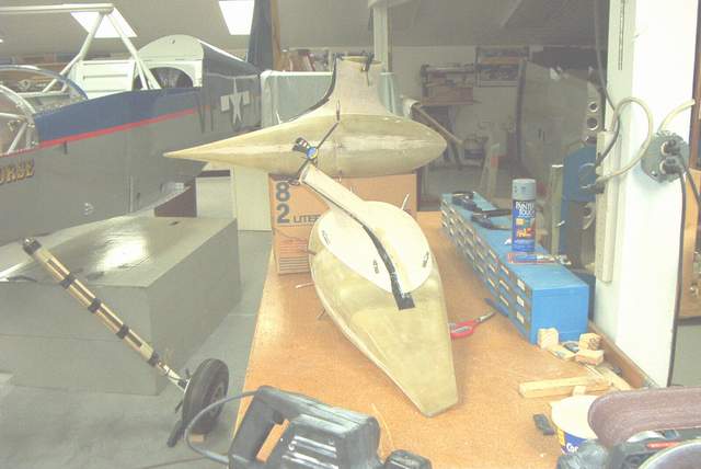
 Fear not. This ugly thing is just a scrap aluminum to mockup the wheelpant
support bracket. The real bracket will be made from .060
4130 steel. (I later heard that Mark is using .093 steel now.)
Fear not. This ugly thing is just a scrap aluminum to mockup the wheelpant
support bracket. The real bracket will be made from .060
4130 steel. (I later heard that Mark is using .093 steel now.)
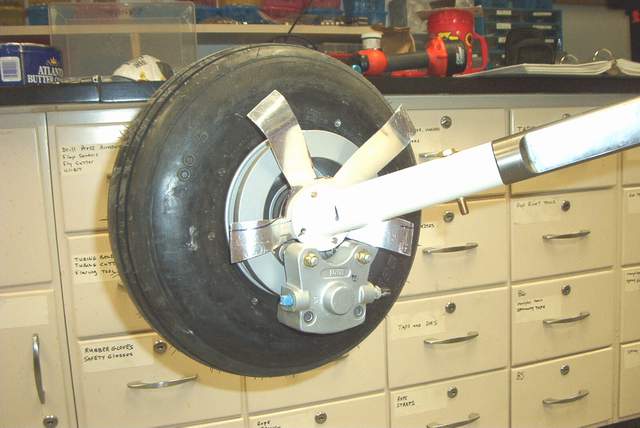
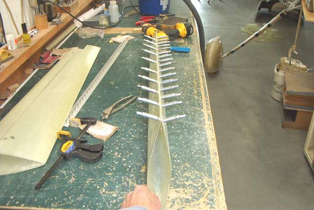
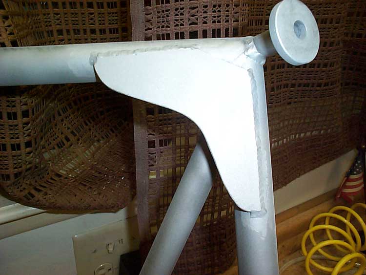
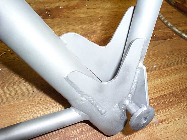
 3-6-03: Cutting out the wheelpant support (the starfish) and installing it
between the axle and axle socket. Nutplates to be installed at the end of
each leg.
3-6-03: Cutting out the wheelpant support (the starfish) and installing it
between the axle and axle socket. Nutplates to be installed at the end of
each leg.
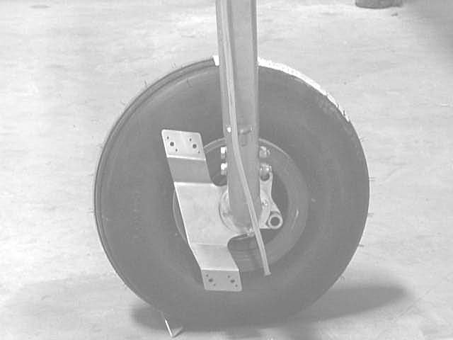
 There needs to be a bracket on the outboard side of the wheel too. This
4130 will soon be cut and welded into a nice bracket.
There needs to be a bracket on the outboard side of the wheel too. This
4130 will soon be cut and welded into a nice bracket.
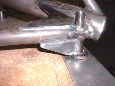
 Here's the super sturdy outer wheelpant bracket. It will have 2 nutplates
installed later. I plan to use 2 screws here instead of 1 so there will be
less tendency for the wheelpant to twist.
Here's the super sturdy outer wheelpant bracket. It will have 2 nutplates
installed later. I plan to use 2 screws here instead of 1 so there will be
less tendency for the wheelpant to twist.
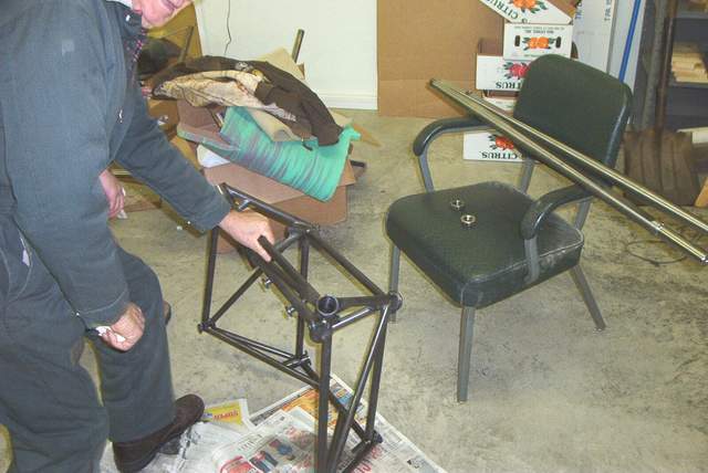
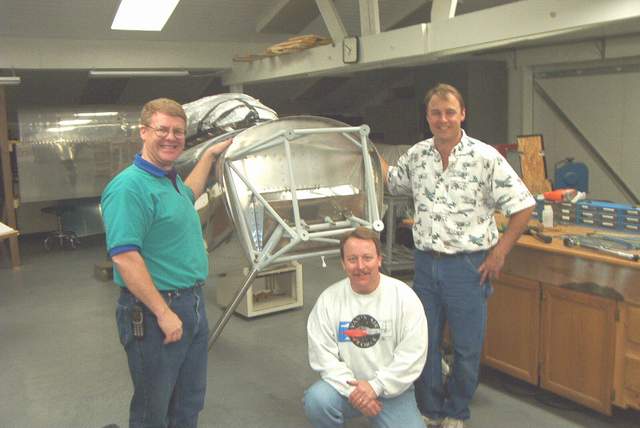 The crew that installed the EM to the fuselage. FINALLY! It's on it's on
gear. Left to right: John Crabtree, Jim Truitt, and Vince Frazier.
I can't help but notice that this project is making my hair slowly fall out.
Doh!
The crew that installed the EM to the fuselage. FINALLY! It's on it's on
gear. Left to right: John Crabtree, Jim Truitt, and Vince Frazier.
I can't help but notice that this project is making my hair slowly fall out.
Doh!
Gear leg fairing installation:
12-3-03:
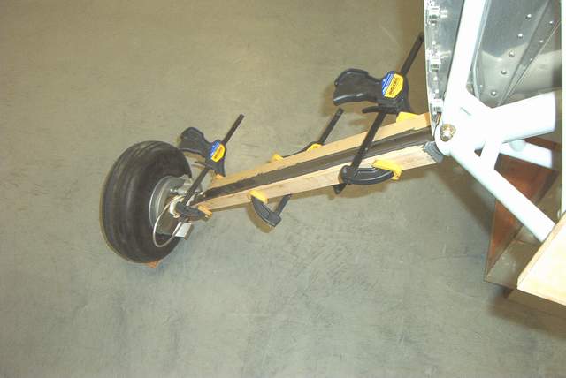
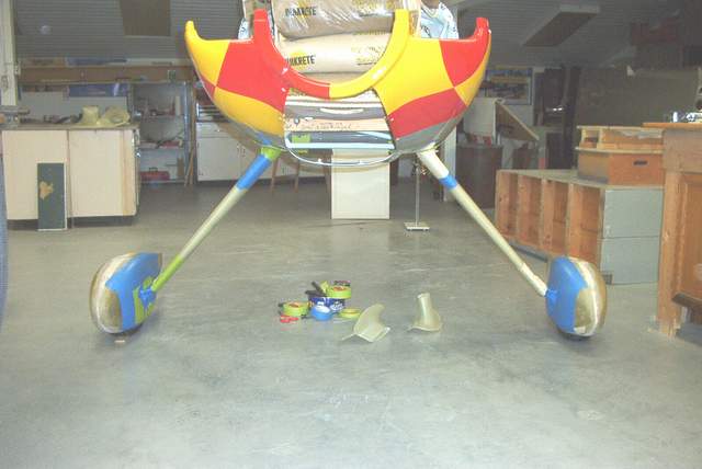
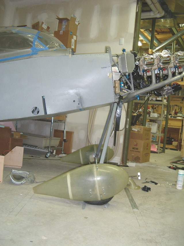
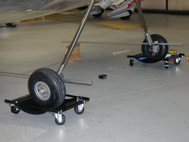
I had already done a rough trim of the wheel pants while the EM was on the bench. Now it's time to continue the installation with the wheels on the floor and some weight added to the fuselage to approximate the normal flying weight.
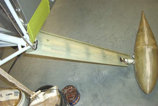
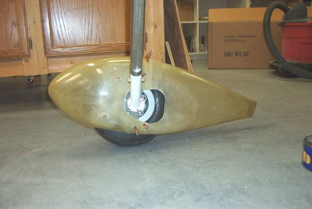 I mounted the wheelpants while the EM was clamped to the bench. Looks like
my WAG (wild arsed guess) about where to position the aft end of the pant was
about right.
I mounted the wheelpants while the EM was clamped to the bench. Looks like
my WAG (wild arsed guess) about where to position the aft end of the pant was
about right.
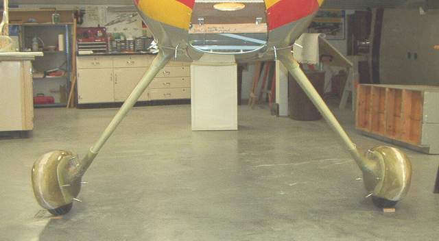
 The camber of the wheels is readily apparent in
this shot. Not much weight on them yet though.
The camber of the wheels is readily apparent in
this shot. Not much weight on them yet though.
 11-17-03:
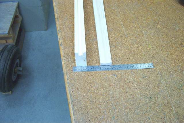
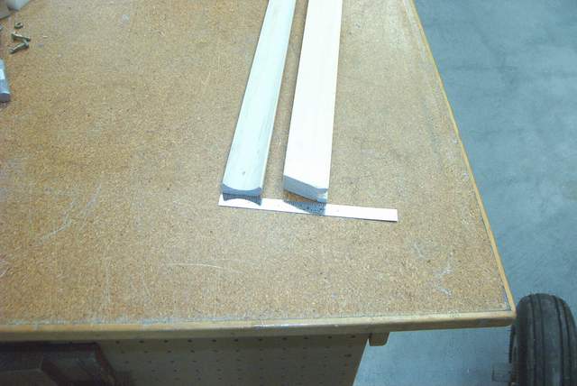
I made my gear leg stiffeners out of ordinary pine trim stock from Lowe's or
Home Depot. One piece, I would call it "cove molding", already had the 1
1/2" inside radius that conveniently fits the gear leg radius. I tapered it as
shown above. The other piece of trim stock was grooved to cover the 1/4"
brake line (which I later changed to a teflon/ss line and cut the solid line off
leaving the wreckage inside the stiffener.)
11-17-03:
I made my gear leg stiffeners out of ordinary pine trim stock from Lowe's or
Home Depot. One piece, I would call it "cove molding", already had the 1
1/2" inside radius that conveniently fits the gear leg radius. I tapered it as
shown above. The other piece of trim stock was grooved to cover the 1/4"
brake line (which I later changed to a teflon/ss line and cut the solid line off
leaving the wreckage inside the stiffener.)
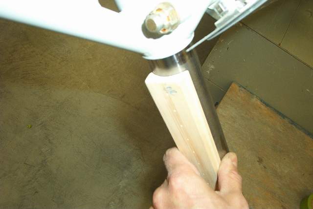
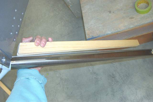
 Fitting the molding. I found that it was very easy to plane the aft
stiffener to have an airfoil shape to it. It is helpful to do this so you
have more room to fit the GLFs later. It doesn't show up in these pictures
though.
Fitting the molding. I found that it was very easy to plane the aft
stiffener to have an airfoil shape to it. It is helpful to do this so you
have more room to fit the GLFs later. It doesn't show up in these pictures
though.
 ProSeal and clamps. The wood simply aligns with the flats on the gear leg.
 Keeping the weight off until the ProSeal sets... about a week in my cool 60
degree shop.
Keeping the weight off until the ProSeal sets... about a week in my cool 60
degree shop.
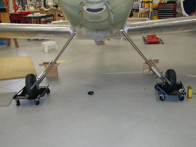
 According to John Harmon, Mark Frederick, and other experts, you are supposed to
have the plane loaded to approximate flying weight before installing the gear
leg fairings (GLF). You'll see why in a minute. I used sandbags from
Home Depot's aircraft supply aisle, 1200 pounds of them. You need to load
them in a balanced fashion so you can pick up the tail and roll the airplane
around a bit to straighten out the wheels. So, don't put it all inside the
cockpit.... and don't put too much on the nose OR THE TAIL WILL JUMP UP AND HIT
THE CEILING!! No, I didn't do that, but it is VERY possible. I put
500# in front of the firewall and 700# in the cockpit.
According to John Harmon, Mark Frederick, and other experts, you are supposed to
have the plane loaded to approximate flying weight before installing the gear
leg fairings (GLF). You'll see why in a minute. I used sandbags from
Home Depot's aircraft supply aisle, 1200 pounds of them. You need to load
them in a balanced fashion so you can pick up the tail and roll the airplane
around a bit to straighten out the wheels. So, don't put it all inside the
cockpit.... and don't put too much on the nose OR THE TAIL WILL JUMP UP AND HIT
THE CEILING!! No, I didn't do that, but it is VERY possible. I put
500# in front of the firewall and 700# in the cockpit.
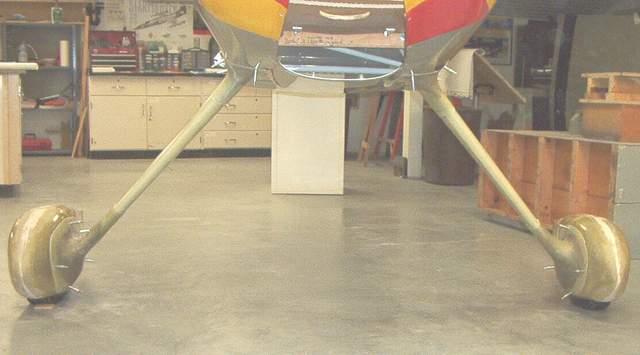
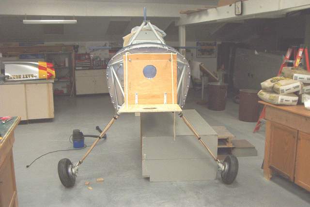 No load
 1200# of sandbags added. Quite a difference!
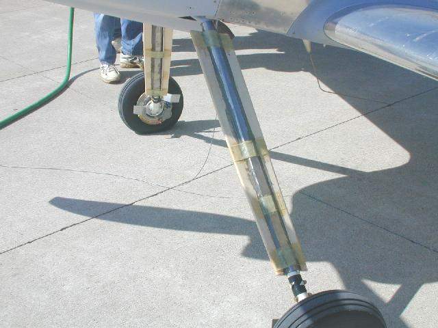
 A shot showing the gear leg shimmy dampers. Nothing fancy, just some pine
trim boards from Home Depot's aircraft supply aisle. Who knew that they
had so many airplane parts?
A shot showing the gear leg shimmy dampers. Nothing fancy, just some pine
trim boards from Home Depot's aircraft supply aisle. Who knew that they
had so many airplane parts?
The pine was ProSealed to the gear leg and wrapped with a few layers of fiberglass. I think that the ProSeal alone would probably hold the dampers in place, but the FG is easy to add.
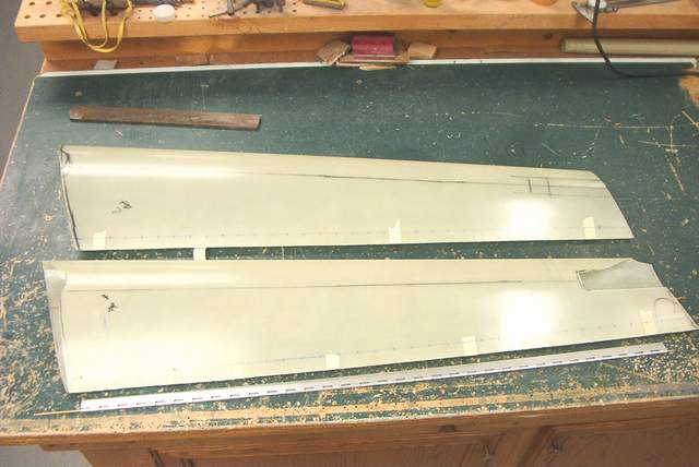
 Here's a straight edge held against the gear leg. Look how much bow there
is.
Here's a straight edge held against the gear leg. Look how much bow there
is.
 The bowed gear leg inside the straight GLF. Now you can readily see why
you need to trim some notches out of the TOP side of the GLF. Otherwise
the gear leg will never fit inside the GLF. And you will likely kink the
GLF on your first hard landing... or so I'm told.
The bowed gear leg inside the straight GLF. Now you can readily see why
you need to trim some notches out of the TOP side of the GLF. Otherwise
the gear leg will never fit inside the GLF. And you will likely kink the
GLF on your first hard landing... or so I'm told.
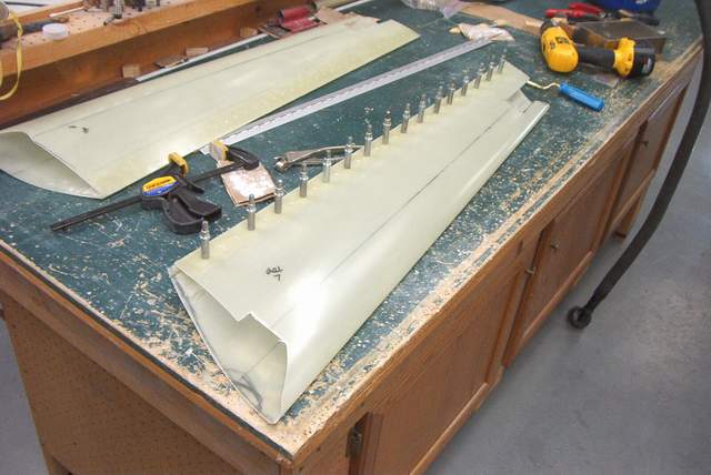
 Notches cut to allow the bowed gear leg to fit inside the GLF.

 The hinges are positioned so that the trailing edge will close nice and snug...
but not so tight that you can't get the pins in. I can't say exactly how
to do this... just use your MK 1 eyeball and give it a go. Just like
on the cowl hinge, you can use an exacto knife to clean out the uncured JB Weld
that glues the hinge to the fiberglass. The rivets, well, I consider them
secondary to the JB. BTW, use dead soft rivets in fiberglass.
The hinges are positioned so that the trailing edge will close nice and snug...
but not so tight that you can't get the pins in. I can't say exactly how
to do this... just use your MK 1 eyeball and give it a go. Just like
on the cowl hinge, you can use an exacto knife to clean out the uncured JB Weld
that glues the hinge to the fiberglass. The rivets, well, I consider them
secondary to the JB. BTW, use dead soft rivets in fiberglass.
 Well, lookee there. They seem to fit. As you can see in the second
picture, the hinge pins (2 per side) are installed from the middle. The
bottom trailing edge has a notch cut out of it just to access the pins.
I'll either make a little cover for it, ignore it, or maybe just put a piece of
tape over it. I haven't decided yet, but a small cover seems likely.... aw
heck, a piece of tape will do just fine.
Well, lookee there. They seem to fit. As you can see in the second
picture, the hinge pins (2 per side) are installed from the middle. The
bottom trailing edge has a notch cut out of it just to access the pins.
I'll either make a little cover for it, ignore it, or maybe just put a piece of
tape over it. I haven't decided yet, but a small cover seems likely.... aw
heck, a piece of tape will do just fine.
 Tape over everything and then apply a coat of PVA mold release.
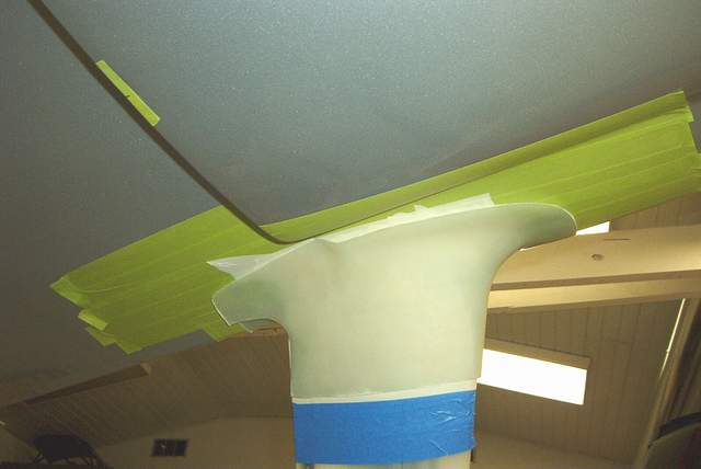
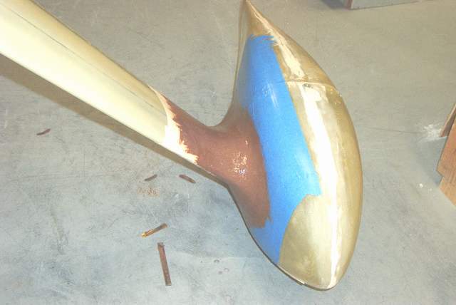
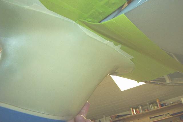 Mark's intersection fairings looked fine on the outside, but the inside didn't
fit around the cowl very well. This was my fault because I fitted my cowl
up tight against the belly.
Mark's intersection fairings looked fine on the outside, but the inside didn't
fit around the cowl very well. This was my fault because I fitted my cowl
up tight against the belly.
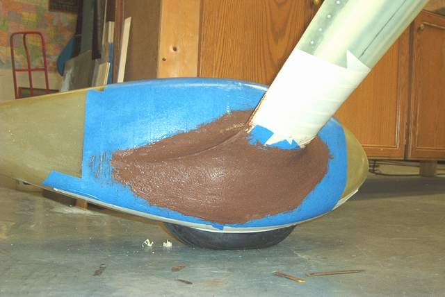


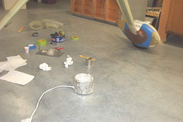
 Smear on the clay. Actually this is some stuff I borrowed from the art
department. It's call Schmitt wax because calling it sh*t wax doesn't
sound very polite. It's made from axle grease, sand, microcrystalline wax,
and who knows what else. But it works very well.
Smear on the clay. Actually this is some stuff I borrowed from the art
department. It's call Schmitt wax because calling it sh*t wax doesn't
sound very polite. It's made from axle grease, sand, microcrystalline wax,
and who knows what else. But it works very well.
The key to getting a smooth mold is to use a 2" chunk of hacksaw blade as a scraper to knock down the high spots.
 Ready for fiberglass..... yuck. Can you believe some people actually build
the entire airplane out of that sticky, nasty crap? I skipped the
pictures of laying up the fiberglass. Why? Well, I didn't want to
get resin on my camera! And because I get impatient when doing
fiberglass....grrrrrr.
Ready for fiberglass..... yuck. Can you believe some people actually build
the entire airplane out of that sticky, nasty crap? I skipped the
pictures of laying up the fiberglass. Why? Well, I didn't want to
get resin on my camera! And because I get impatient when doing
fiberglass....grrrrrr.
 Here's a shot with the sand bags taken out of the fuselage. FWIW, the
fuselage weighs about 200 pounds empty. The fairings gap just a little on
the trailing edge when the gear legs flex inward, but that is expected.
And since I haven't made any sort of fastener for the trailing edge yet, I'll
remedy that minor problem during the finishing and painting.
Here's a shot with the sand bags taken out of the fuselage. FWIW, the
fuselage weighs about 200 pounds empty. The fairings gap just a little on
the trailing edge when the gear legs flex inward, but that is expected.
And since I haven't made any sort of fastener for the trailing edge yet, I'll
remedy that minor problem during the finishing and painting.
1-1-04:
A new year already! And I'm still working instead of flying! Doh!
 Hanging out on a convenient protrusion while the JB Weld sets.
 Finishing the edge of the LGIFs with flox, epoxy, tape and curse words.
The curse words don't show up in the picture, but if you call me I'll be glad to
shout them for you. I hate fiberglass until it's finished and even then I
only tolerate it because it's a necessary evil.
Finishing the edge of the LGIFs with flox, epoxy, tape and curse words.
The curse words don't show up in the picture, but if you call me I'll be glad to
shout them for you. I hate fiberglass until it's finished and even then I
only tolerate it because it's a necessary evil.
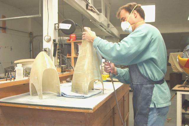 Sanding and filling. Repeat until everything is perfect OR until you get
tired of it and say " #$%* it! That's good enough." I'm not after any
trophies and that last 5% of finishing fiberglass can take 50% of the time... if
you let it.
Sanding and filling. Repeat until everything is perfect OR until you get
tired of it and say " #$%* it! That's good enough." I'm not after any
trophies and that last 5% of finishing fiberglass can take 50% of the time... if
you let it.
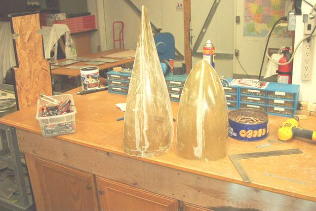
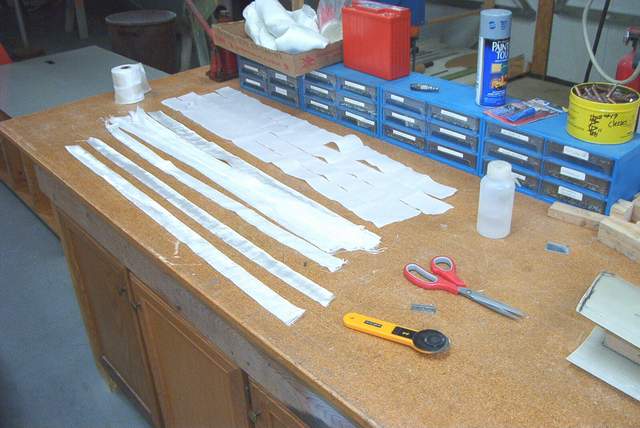
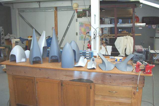 A bunch of primed fiberglass parts awaiting the final paint. Those three
lighter colored pieces on the left side are Jim Truitt's RV-8A wheel fairings
which were damaged when he hit a baby stroller, wheelchair, or something or
other. Maybe it was an orphanage....I can't remember.
A bunch of primed fiberglass parts awaiting the final paint. Those three
lighter colored pieces on the left side are Jim Truitt's RV-8A wheel fairings
which were damaged when he hit a baby stroller, wheelchair, or something or
other. Maybe it was an orphanage....I can't remember.
I suppose my fiberglass skills must be minimally adequate, because he trusted me to repair and repaint the parts. They look good too! Vince *end of comment*
More gear leg fairings:
 Jim Stone's HRII
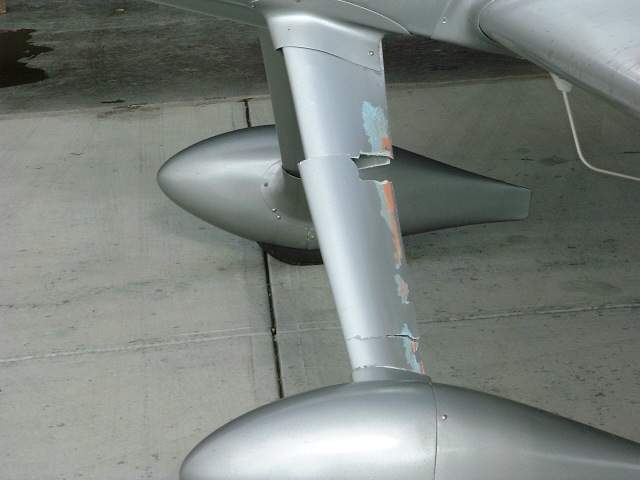 Eric Hansen's gear leg fairing fluttered and tore itself up. Eric had
bonded the trailing edge together. Eric mentioned that he hadn't put
any of the Great Stuff non-expanding foam at the top and bottom as required.
Eric Hansen's gear leg fairing fluttered and tore itself up. Eric had
bonded the trailing edge together. Eric mentioned that he hadn't put
any of the Great Stuff non-expanding foam at the top and bottom as required.
Jim Cash did his glf's this way: Tom and Guys, I promise not to repeat this again. If you will install the gear leg fairings using an aluminum hinge at the back, running the full length of the faring, and use either non expandable or low expandable foam sprayed as far down as possible on both ends of the fairing (probably a 6'' long layer) they won't come off. I take the black airplane out to over 250 indicated on just about every flight (4 to 5 Gs are routine) and the foam has never even broken loose. Its just my opinion, but with over 100 hours with this installation (and I fly an airplane aggressively---Lui can attest to that) I think the product is OK if installed this way. The aluminum strips on both sides provides a little more rigidity, and the foam seems to hold the whole thing in place very well. If you want more detail email me offline at jcash@centurytel.net. Jim Cash *end of comment*
Today I lost my left gear leg fairing (GLF) to flutter. I was at 220 KIAS, 1 G flight, in a slight dive when I felt a buzz in the airframe that lasted about 1.5 seconds, felt the airplane yaw slightly, then smooth again. I new something had just fluttered and departed the plane, I did not know what but suspected a GLF or wheel pant. Sure enough when I landed the fairing was 80% gone, and a good chunk of the wheel pant intersection fairing also. This will require a complete rebuild of the fairings and wheel pants on that side. It just exploded off of there. Luckily there was no other damage, and the landing was uneventful. I am very happy that is all it was, but very unhappy I will be gluing, sanding and painting again.
I had previously tested out to 250KIAS and 4 G, and routinely operate above 220-230 KIAS so I thought I was safe from the flutter demon. My preliminary thoughts are that with flight time and landings, the fairing has been getting looser and looser and the original expanding foam had completely let go of its holding power some time ago. I think my original tests were done when the expanding foam was still holding, so everything was solid. The right GLF can be moved slightly in rotation about the gear leg and I think this is what set up the left one to flutter. I don't recall one GLF being looser than the other, but it probably doesn't take much.
So for those flying and still building, no free play in rotation for the gear
leg fairing seems like a good idea. What I plan on doing different to prevent
this from re-occurring is to glue foam rubber weather stripping inside the
fairings to press against the gear leg fairing. This will insure a tight fit of
the intersection fairings and the GLF and damp any motion before it can get
started yet still allow the required motion between the parts required for gear
leg flexure. Once the expanding foam gets too loose and your intersection
fairings loosen up, problems can occur. I just turned 80 hours a couple flights
ago and was starting to think I had a pretty reliable airplane. Greg
Nelson N144X *end of comment*
I am happy with my glass fairings. Yes I did crack the ones on my HRII but it was a bad landing, and I am sure that the metal fairings, even with the split, might have shown some damage. I was able to remove the fairings, glass over the crack and repaint them, good as new.
The key to these things, in my opinion, is to use the hinge method of attachment and foam top and bottom. Before you install them, line the top and bottom of the faring with packing tape. This way if you ever have to take them off the foam will stay with the gear leg and you can easily remove the faring. This will mean that your "repaired" fairing will still fit the upper and lower gear leg intersection fairings. They might not if you had to add new foam.
I have about 600 hours in three different rockets and I only have had one small problem with the fairings. The metal fairings on my RV4 were showing wear at 300 hours and many that you see at airshow look pretty crappy after a few hundred hours.
Gear leg stiffeners:
 I did like the basswood stiffeners and I am thinking of adding them to my HRII.
I think that they are a must, even with the Indy Mount. They are simply one half
inch thick boards about two and a half inches wide. I glued them on, front and
back, with ProSeal and then wrapped the leg in four locations with glass to
secure the whole mess. Glass over the entire leg will crack and might let the
stiffeners work loose.
I did like the basswood stiffeners and I am thinking of adding them to my HRII.
I think that they are a must, even with the Indy Mount. They are simply one half
inch thick boards about two and a half inches wide. I glued them on, front and
back, with ProSeal and then wrapped the leg in four locations with glass to
secure the whole mess. Glass over the entire leg will crack and might let the
stiffeners work loose.
Install the dampeners with as little weight as possible on the gear legs. Install the gear fairings and upper and lower gear fairings with the plane loaded to simulate at least full fuel and pilot. Tom *end of comment*
Changing Gear leg sockets:

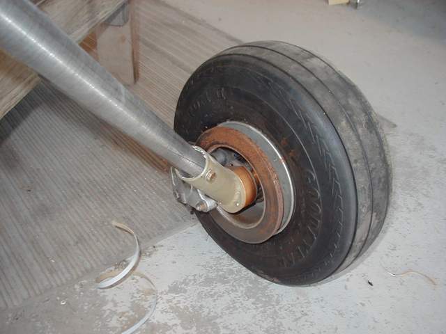
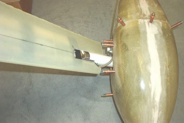
 We made a jig to allow fitting of new axle flanges to existing holes.
Aluminum square tubing clamped to the brake disks allowed measurements against a
centerline and each other.
Blue skies Bob Wahl
We made a jig to allow fitting of new axle flanges to existing holes.
Aluminum square tubing clamped to the brake disks allowed measurements against a
centerline and each other.
Blue skies Bob Wahl
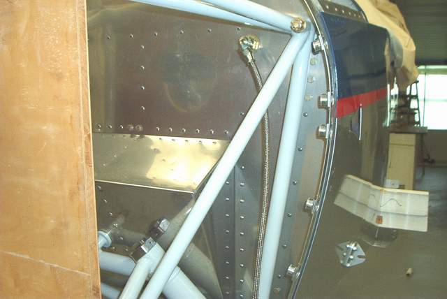
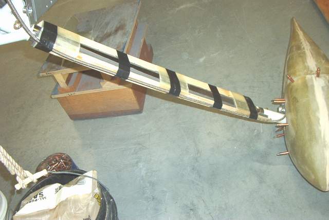
Tailwheel:
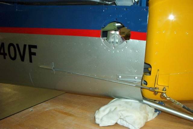
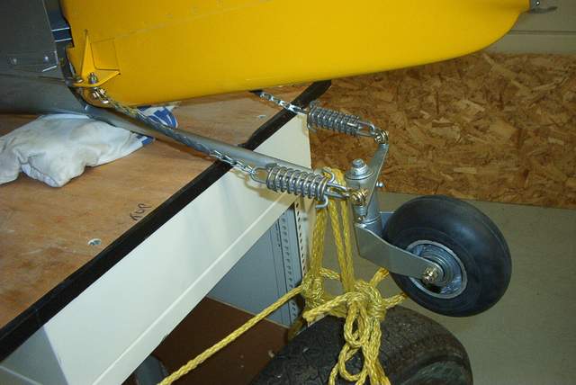
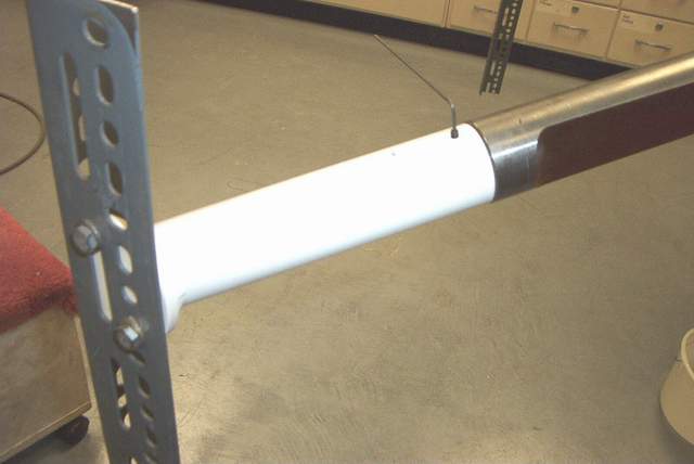
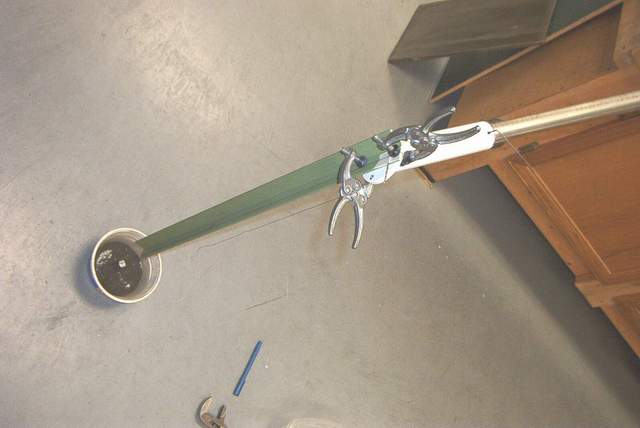
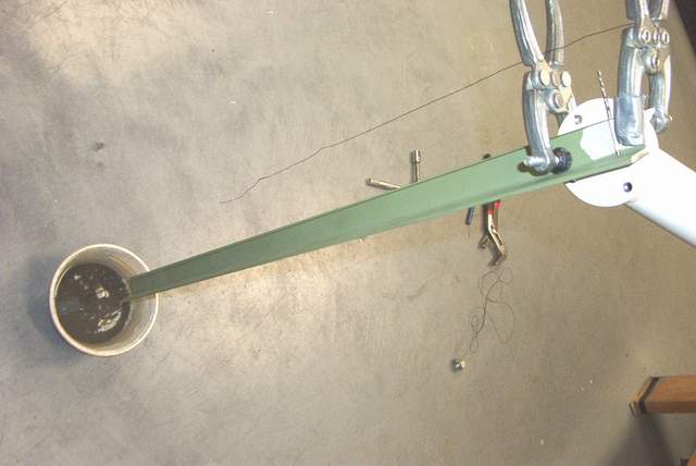
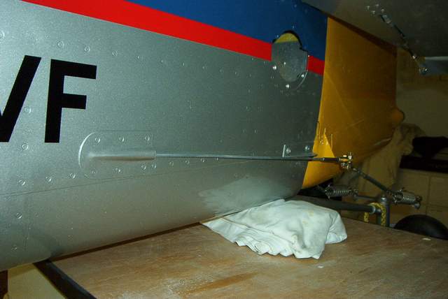 Here's
a few shots of the completed tailwheel area. You can see in the first pic
that I had to grind an extra hole in the rudder bottom fiberglass cap to clear
the bolt heads holding the VS on. The second pic shows a tidy way to cover
the chain using shrink tubing. The third shows a no-cost cable fairing
easily made with two blocks of wood with a rod stuck through them diagonally.
Here's
a few shots of the completed tailwheel area. You can see in the first pic
that I had to grind an extra hole in the rudder bottom fiberglass cap to clear
the bolt heads holding the VS on. The second pic shows a tidy way to cover
the chain using shrink tubing. The third shows a no-cost cable fairing
easily made with two blocks of wood with a rod stuck through them diagonally.
I want to pass on a little tidbit here about the bolt that holds the tailwheel spring to the tailwheel weldment. I drilled mine per Mark's instructions and found that the bolt went in too easily--this should be an interference fit (once again, my savior the "big-ass" hammer should be used to put the bolt in). I wrapped a piece of scrap aluminum around the tailwheel spring and could twist it with a pair of vise-grips. Not good! If there's any play here, the bolt can eventually fail or the hole will become elongated. I have heard of failures in these bolts on RV's . Rather than taking my chances with a larger bolt and it too not being correct, I decided to fix it with a taper pin which worked out very well. Here's the recipe:
AN386-2-9A taper pin (aircraft spruce)
AN975-3 taper pin washer (aircraft spruce)
B&S #2 taper pin reamer (http://www.mscdirect.com/MSCCatLookup2.process?MSCProdID=02054021) (1/2 the price of AC$)
12" long tap handle (http://www.harborfreight.com/cpi/ctaf/Displayitem.taf?itemnumber=45206)
The taper pin has the advantage that if the pin ever loosens up, you can just tighten up the nut and things should be snug again. The taper pin is an odd-sized Browne & Sharpe #2 taper, so don't confuse it with other -2 tapers.
I highly advise that the final hole size should be reamed with a hand-reamer .001-.002 under-size even if you don't use a taper-pin. There are too many variables with drilling to final size with a hand drill. Bob Japundza
*end of comment*Miscellaneous:
Q: Speaking of toe-in toe-out. How is it measured. 1/16 of an inch means what?
A: (This refers to HRII gear legs) Are you going to drill the gear legs with the engine mount on the fuse?? IMHO, a bit out of sequence, but possible. I set mine up with 1/8" (1/16" each side), and it wasn't quite enough. I'd say 3/16" might be closer to optimal.
Toe in means just what it sounds like. Stand with your feet straight ahead. Now move your toes closer together without moving your heels. That's toe in and that is what you want on your taildragger... just a little though. Toe out makes 'em squirrelly on the runway. *end of comment*
Engine mount and gear leg problems:
If you're not intimately familiar with what is going on here, please read this entire section and talk to Mark Frederick before making hasty decisions or derisive comments. Also, much of this is ancient history now (3-3-03) as some suitable fixes have been found.
The following few paragraphs talk about a problem that some of the F-1's have been having. The gear legs get slightly loose in the gear leg socket. Although annoying, these problems are not unexpected (as with anything new) and will be overcome with a little elbow grease! Aw heck, my Harmon flying buddies have had gear problems also. It's the Achilles heel of the Rockets! Vince
Ok, the gear is drawing up into the socket. This socket is a standard Morse taper, the same kind that machine shops use to hold tools in place on lathes, I find it hard to believe that the leg is drawing up into the socket unless, like in my case, the socket was not perfect to begin with. When I was fitting my gear legs I was not happy with the amount of thread that was showing above the nut. Removing the leg I found that the surface of the tapered socket was not all that smooth. I purchased a little hone from my auto store, these are the ones that are used to hone the inside of brake cylinders on cars, and I honed the sockets. This did smooth the socket to a more satisfactory level and the gear leg did draw up farther into the socket. I was able to gain one thread on one leg and almost two threads on the other. I did not remove anything from the socket other than some high spots and tooling marks. I have two engine mounts here and they are both the same way. I have no way of measuring the surface of the socket to determine if it is true at this point, but it is much better.
There are some other possible reasons that could explain the gear sliding further into the socket. The socket could be expanding and or the gear leg could be wearing. This seems very unlikely with so few hours. If you did not remove the powder coat from under the nut it might seem like the gear leg was coming up when it was only the powder coat compressing. I measured the depth of the powder coat at .015 thou. This should be removed from any spot on the engine mount where there is a fastener attached. I am not a big fan of powder coating as it is very difficult to see what is happening to metal under the product, cracks do not always show through.
It would be nice if we could get the Czech engineers to respond to this issue as it really is something that is out of my area of experience. Perhaps Wess Triff could comment on my speculations. This puzzle will be solved. Tom Martin
When I mounted the legs on the engine mount I noticed I could check the nuts once a week and I could turn it about 1/8" every time. It finally got to a point when it stop turning. Then I had the need to remove one of the legs. Guess what? It is a mother to remove. It appears, once it is there, it really wants to stay there. I hope I don't ever have to take those out.At the beginning stages of fitting the gear legs I also removed the powder coating that I believed was in the way. I also found some welding residue on the inside of the socket that needed to be smooth out. These were not allowing the gear leg to go all the way in. I could put the nut but I knew it needed a bit more thread as Tom mentioned here. Once those rough spots were taken care, I could get more thread to show up. It now appears to be all the way in.
Luis 21 *end of comment*I agree with Tom- the fact that the nut did not move throws out the torque issue and sheds new light on this. All fasteners I deal with are seated on parent material, and the inside finish of the mount sounds a bit iffy, so I'd clean off the mating surfaces (inside the Morse taper and on the mount-nut surface) and let the gear settle in (as Luis suggested). Keep us posted on the results! Wes Triff #14 *end of comment*
Hi guys, I think this one is worth filing away for future reference. While at OSH I talked to Snap-on tools and ordered a special crow's foot for the gear leg nuts (3/8'' drive and 1 5/8'' opening). Eric Hanson had mentioned this to me some time ago, and it works. Every time I check the nuts they are loose, even with tight safety wire. With the engine on and plumbed its a bear to get to them with a socket. However, with the crow's foot its a piece of cake, and I can use it with my torque wrench. Cost was about $30. Jim Cash *end of comment*
Engine Mount update 5-20-02 Hi
Fellas: Well, we have the results of the analyzing of the Engine mount and gear leg
assembly. This testing showed some surprising results, to say the least. I will make the
appropriate changes to the manual.
In the meantime, please note the results and clean all debris and grease from the lower
socket area as noted. We will come up with the proper reaming tool as quickly as
practical, and distribute this tool (or tools) among the flying ships first, and then to
the ships which are closest to flying, and then to the remainder of you builders.
Cheers!
Mark
This letter from Petr was attached:
Hello Mark,
HPAI ordered in Aeronautical Research and Test Institute an analyze of possible reasons
for cracks creation in F1 engine mount. Here are
results of this analyze and some possible solution recommendations:
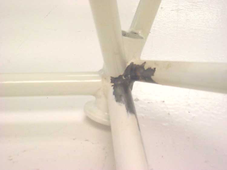
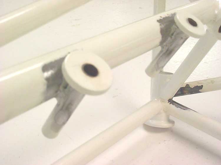
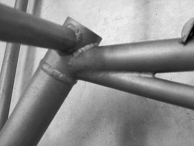
1) The main reason for cracks creation in upper area of main leg holder in F1 EM is a
shimmy effect of leg during taxing. The cracks have two cross direction which show us that
the leg is loaded by torque and this torque was supported only in upper area of EM by slot
and nut.
HPAI note: All notes about nut loosing and problems with their fixing support this idea.
From Bob Japundza: The real problem is the socket; the mounts breaking in other areas are a consequence. A Morse taper is a locking taper. It will lock the gear in place and keep it from twisting torsionally. Without a precise fit (reaming), the Morse taper will not do its job. If the Morse taper is not doing its job, all of the twisting loads get transferred to the cap on top of the socket. Since that piece is welded only to .050 thick tube (the tube welded between the Morse tapered piece and the top cap) it is likely that twisting in this tube will occur. And that is where the mounts have broken. The pictures of the broken mounts I've seen show the welds broke out of the gear leg sockets where it is welded to the .050 section. The gear leg sockets should have been reamed from the factory after welding to begin with, but that's another story. The engineering analysis that was done by HPA outlines all of this.
My $.02 this subject: The stronger you make the mount the better. This will have an effect of making the firewall stronger. The engine mount should not "give" in any way, shape, or form. This is why the gear legs are flexible, and why there are rubber mounts for the engine to sit on. Those things are supposed to "give". Not the mount. Not the firewall. So, it is my opinion the gussets help strengthen the mount, and consequently, the firewall and forward fuselage. How else do you make something more resistant to breakage? Probably a little overkill but that's ok. At the very minimum I believe gussets are necessary at the firewall attach bolts and the "pads" that rest against the firewall.
The mounts that haven't broken apparently have had a good fit to begin with in the Morse taper. Some luck can play into that equation as well. The taper warps/shrinks when the engine mount is welded together. That's not to say that "yours" may fit well, but reaming will guarantee a good fit. Reaming the sockets for a good fit is probably the best way to help prevent future problems. They need to be put together dry.
Going forward, I believe the sockets should be redesigned so that the .050 wall tube is thicker, say .100, and made of one piece with a top cap welded on. Van's gear leg sockets are this thick. And they're carrying a considerably less load. With the sockets being thicker, it is less likely that the sockets will stretch allowing the gear legs to settle, and there is more material to counteract the compression/twisting loads at the top of the sockets where they are welded to the other tubes (and the bottom for that matter.) The socket taper ID should be undersize when they are initially machined so that when the final reaming is done, 100% contact area can be achieved, without the gear leg bottoming out at the top cap. Right now its is too easy to take out too much when reaming, resulting in the gear leg bottoming out at the top. With that in mind it is nearly impossible to get 100% contact area at the bottom, because you can screw things up worst if you try to get better contact area when reaming. And, since the top of the tapered piece is welded around its diameter to the .050 piece, the weld shrinks the socket there which may be distorting (stretching) the bottom of the sockets, which may be another reason why guys aren't getting contact down at the bottom after reaming. So be careful there, guys. It's very likely that you won't be able to achieve 100% contact area esp. at the bottom...
I could go on and on and on this subject...sorry for the long post. Myself and Jim Winings have probably analyzed this thing to death. Bob Japundza *end of comment*
Mark asked me to outline how I reamed my gear leg sockets. I will do so not as an "expert" but a first time builder who approached the problem. Apparently someone attempted to ream the sockets without using cutting lubricant on the reamer. Result: ruined reamer.
All credit goes to Tom Martin. I called him on the land line and he was patient enough to coach me prior to the task.
Some history. The builder manual initially called for grease on the gear legs when installing the legs as a final step, with 40 to 50 ft-lbs. of torque. This grease may have presented a physical barrier and prevented complete seating. The welding caused a minute amount of distortion as well the tubes of the gear mount and the interior of the socket. The net effect was less than desirable seating on the number 5 Morse Taper socket and gear leg.
Solution: If the legs were previously installed remove by putting a layer or two of electrical tape on the top of the gear leg after removing the retaining nut. Place a block of wood over the leg top, get Luis' favorite tool, Big Hammer, and strike with vigor. USE CAUTION NOT TO DAMAGE THREADS. I WRAPPED THE TAPE AROUND THE THREADS TO PROTECT THEM.
Clean out that @#$$#%% grease from the socket and gear leg.
Grab your reamer, wipe it down and get all chips from previous use, don't drop it and chip or bugger up the sharp edges. SOAK IT IN CUTTING LUBRICANT AND PUT SOME IN THE SOCKET. LET IT DROOL EVERYWHERE. Cutting oil is a lubricant that allows the sharp edges to cut without excess friction, carries away removed metal and keeps temps down to reduce work hardening, etc. Suitable examples are "kroil", purpose made cutting oil from machine shops, and a simple kerosene used for ALUMINUM cutting (not steel at least by me). Engine oils are too viscous and will not carry away cut material, their role in life is to prevent cutting.
Place reamer in socket and use your 1" socket wrench and turn by hand holding the wrench near the head with one hand turning with the other. USE SYMMETRICAL FORCE ACHIEVED BY THE HAND NEAR THE CENTER OF THE WRENCH. Turn the reamer 5 to 10 complete revolutions. You will hear a high pitched squeal as you go prior to 5 to 10 turns possibly. Stop. PUT IN MORE CUTTING FLUID.
After turning the reamer observe the interior of the socket. You will see shiny spots were the tubes were welded to the socket. That is where you cut. YOU ARE DONE.
I measured my before and after thread length above the cap of the gear leg mount and found a .02" increase after reaming. This 80% contact is a number made up to ensure that you DO NOT REAM TO MUCH PUTTING THE WHOLE GEAR LEG TOP IN CONTACT WITH THE SOCKET. That net result would be the shoulder of the gear leg hitting the top of the gear let mount. All loads would transfer there and not to the Morse taper. Tom Martin came up with 11/16" as a thread length max above the gear leg top to prevent such an occurrence. It is a correct number.
Clean all oil and chips from the tool and interior of the socket. Reassemble and torque to 40 to 50 ft-lbs. This is what is referred to as the dry assembly.
Hope like crazy my un-reinforced, non-gusseted Mk I Mod 0 engine mount doesn't break in service.
Call the folks without email and tell them to use cutting oil, send a carrier pigeon to anyone living on Walden Pond. Hope they don't have a shotgun. Howard *end of comment*
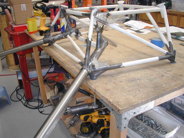
Welding gussets on that #$%^ engine mount (Fall 2002):
Q: I am about to do EM welding and have a question. In my 'archives' I found: "....thermal expansion) of the EM while welding.? It wont take very much for the Em not to fit . Maybe a good idea would to make a 1/4 " plate , bore holes to match the mount, secure the EM to the plate while welding." What is the current thinking/experience? Is the plate or cross-bracing necessary? Dave Bockelman
A: Dave, I had my engine mount reamed and bolted to the fuselage when it was removed for welding. I made a cross brace of 1/8" thick steel flat bar with the cross welded before I took it for mods. When the mods were done the EM fit perfectly. A lot will depend on your welders skill level, where you put gussets and the type of welding done. Tig welding would be most appropriate for this particular job. Tom *end of comment*
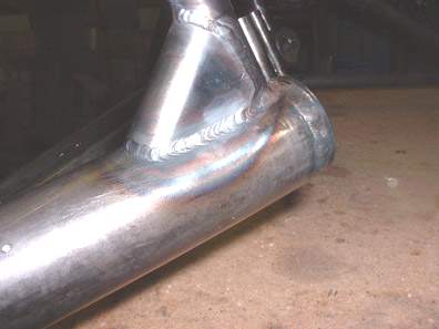
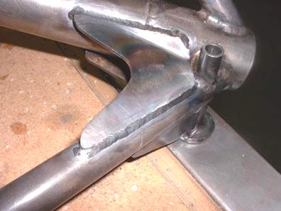
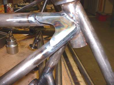
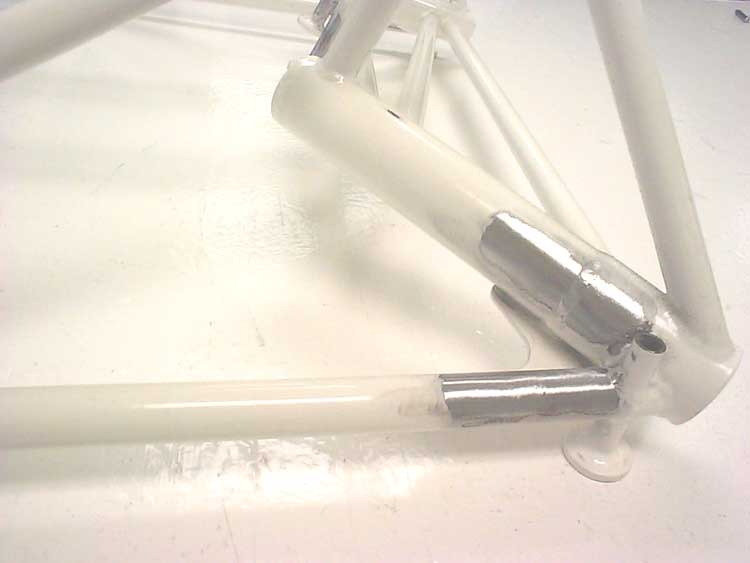
Here's what I did to fix my engine mount. I suggest having the powder coating stripped professionally prior to beginning any work. That stuff is pretty tough and stripping all those tubes by hand is a real pain in the backside.
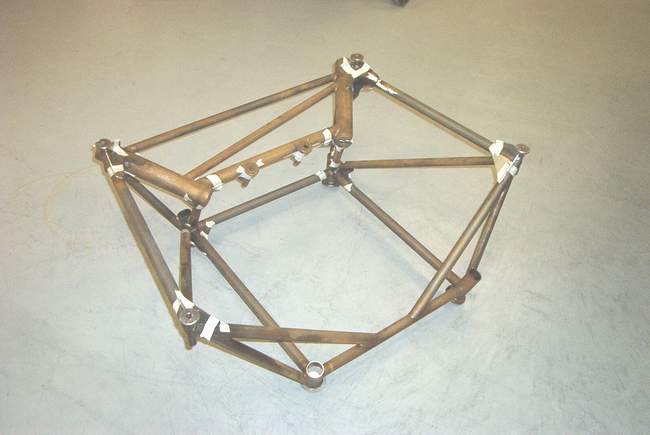
Using the ideas that I got from the work that Tom Martin, Lui Escobar and Bob Wahl did (shown below) I made the gussets shown in the photo below from 0.063 4130 steel.
The gussets were ground as needed to fit then tack welded in place. I plan to do the finish welding ASAP since the 4130 rusts quickly. Afterwards, I plan to have the mount powder coated again. They only wanted $40 to powder coat, which sounded much better than trying to paint all of those tubes.
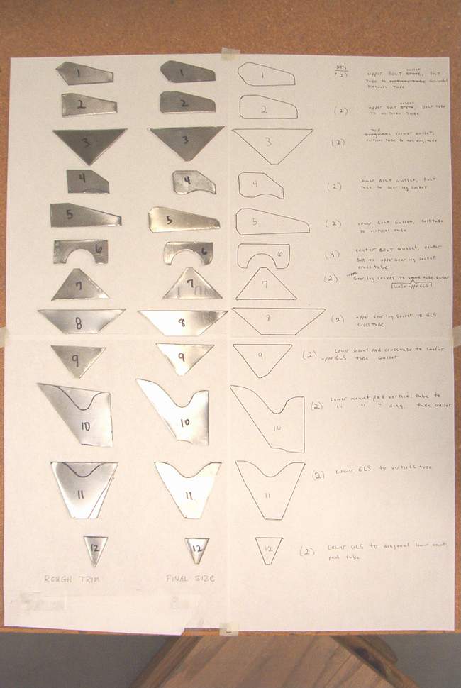
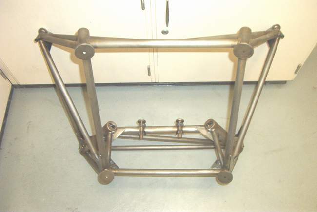
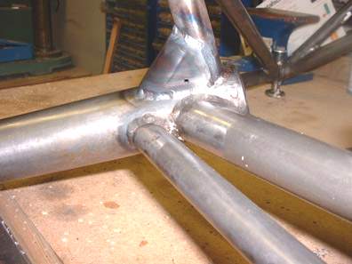
The photos below show the gussets after fitting. They are taped in position so I don't forget which one goes where... a very easy thing to do.

Below are details views. The numbers on the photos correspond to the numbers on the gusset ID photo above. Helps to figure out what goes where.


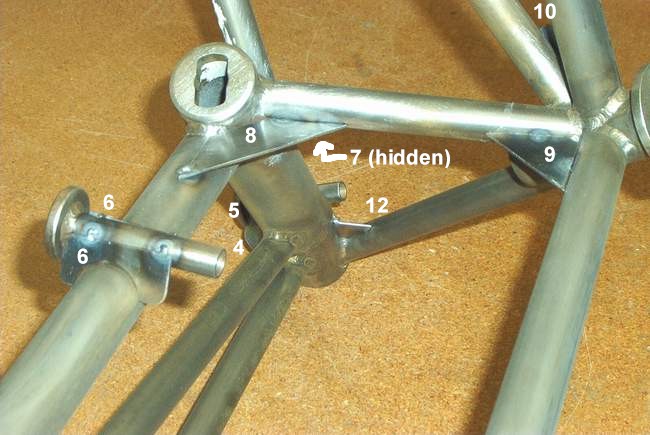
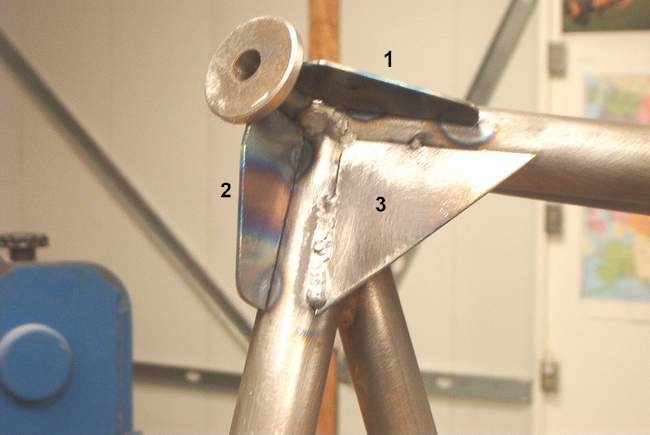
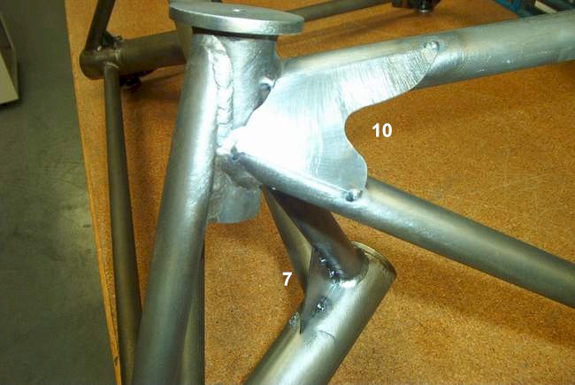
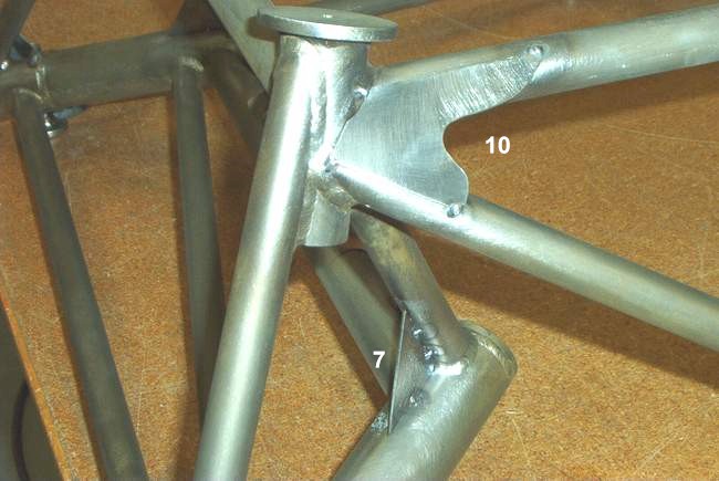
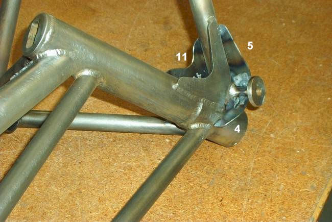
Here's a few shots after the tack welding is complete. The first pic is numbered with gusset IDs.
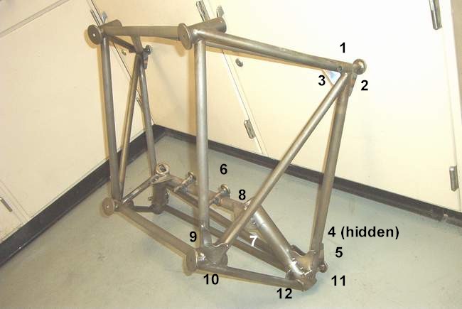
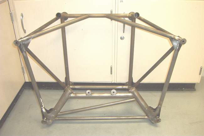
Tom Martin, Lui Escobar and Bob Wahl's works is shown below. I mostly copied what they did. Sure hope it works. Vince *end of comment*

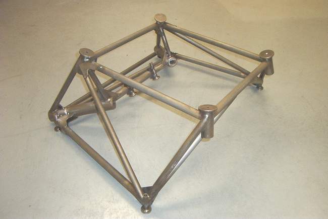
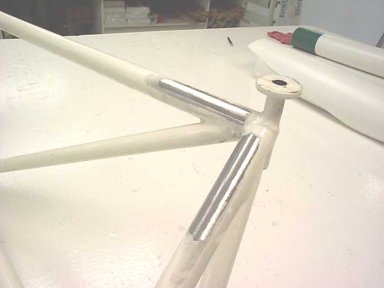
Tom Martin gusseted his EM like this. I don't have any details yet other than these pics. Mark says the gussets are .063 4130 steel. *end of comment*


 Here's some more EM modification pics from Lui *end of comment*
 I finished reaming the gear leg sockets which was not much of a job because I
was able to bolt the mount to a sturdy table. I suggest that everyone check the
amount the gear leg threaded portion that extends above the top of the mount to
make sure that the leg is bearing on the taper and not the bottom of the slot in
the mount.
I finished reaming the gear leg sockets which was not much of a job because I
was able to bolt the mount to a sturdy table. I suggest that everyone check the
amount the gear leg threaded portion that extends above the top of the mount to
make sure that the leg is bearing on the taper and not the bottom of the slot in
the mount.
To new builders: IMHO a sturdy bench such as the one in the photo is essential. Mine has a top that is 4' X 5'6" X 35" high and has a bottom shelf which when loaded up with all your junk keeps the table in place. Use 3/4" particle board and you can screw building templates, bending jigs etc. to it to aid in the building process.
Blue skies, Bob W *end of comment*
Hi Fellas:
If you want to modify your EM before reaming, go to the manual update page & see how it was done on Tom Martins' mount. The CZ engineer (Petr Varadi) had a look, & agreed that if you wanted to do something, this would likely be a good method.
If you have already run the reamer in the sockets, then about all you have available as an option is to weld the small gusset at the lower bolt attach tubes. As this showed up as the highest strain point (in a hard landing), you will get a large benefit from this small mod. No subsequent reaming will be need after this small gusset is welded onto the mount.
We are assembling an F1 here in the shop. It will be run with a non-modified mount first to see how long that may last. The field here is ROUGH, so any faults will show up rather quickly. After that mount shows distress, we'll make repairs (likely to the Martin/Frederick Mk.1 Mod1 status), and see how long THAT lasts. If that one breaks, we'll change to the Mk.2 EM. Sound like a plan to you?
FYI: my Harmon mount went 700 hrs on such a strip, and the F1 mount is considerably stronger. The cracks to the HR mount mimicked the F1 stress damage exactly. I had it rewelded without adding any gussets, though it looks like the M/F Mk.1 Mod1 would have worked there too.
Procedure (after all welding is complete):
ream socket with reamer (use plenty of cutting oil; turn the reamer with a 1" wrench)
stop reaming when sufficient contact is achieved, or 11/16" of thread protrudes from the top of the socket
clean socket & leg thoroughly
re-assemble leg to socket; tighten leg nut to 40 lbs/ft. Safety wire nut.
Cheers! Mark *end of comment*
9-12-02: I have been getting some good flight time in on the F-1 in the last few weeks, and it is really flying nice. I now have just over 60 hours flight time. This plane is an absolute blast to fly.
My crows foot for the upper gear leg nuts arrived from Snap On, so I pulled the cowling to check on firewall forward goodies and of course the gear leg nuts. This crows foot should be standard equipment if you own an F-1. Let me repeat that, If you own an F-1 Rocket, put a crows foot for the nuts in your tool box, you will need it for routine maintenance of the gear legs, reamed or not. There is just no way you are going to be able to check and tighten those nuts in service once the engine is installed and plumbed with out the crows foot. This is important! You can only do so much with channel lock pliers.
I put the crows foot on the nuts and checked the torque. Both were low, but not loose, this after 10 hours from the last time they were checked and tightened. The inspection lacquer was not broken, it is the gear moving up into the sockets. I was able to get another flat on the right nut, and almost three flats or half a turn on the left! I found that I could torque the nuts to 40 Foot/Lbs, then rock the ship back and forth with the wings, and for and aft against wheel chocks then check the torque again and it would be low, just like that. I kept doing that until the torque stopped changing. This was the first time I have been able to do that since I just now got the crows foot. I wish I had it all along. My gear is still working its way into the sockets. I have two threads showing above the nut on the left and 2.5 threads showing on the right. Eventually they will stop moving, but I'm not there yet. An inspection with flashlight and mirror showed no signs of any distress on the engine mount, so good news there. Looks as good as the day it was installed. Just wanted to update everyone on the gear leg status of my ship. Greg Nelson F-1 #8 *end of comment*
Mk II Engine Mount 1-15-03 The Czech crew has a Mk 2 mount in production now to hopefully cure some of the concerns about broken EMs. Here's a few pics:

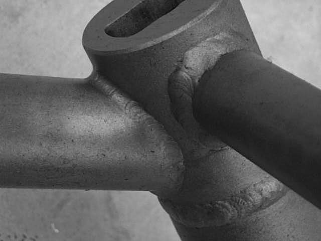

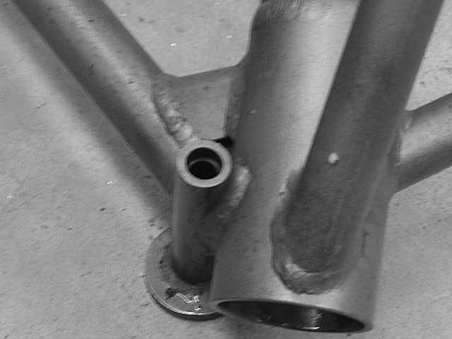
Mk II Engine Mount 6-1-03 If you have a Mk.2 EM, we are requiring that it be converted into a Mk.2 Mod.1 version with the kit supplied by Team Rocket. See the attached photo for an example of the finished product. We will supply 2 sleeves and 12" of 3/4"x.049 4130 tubing in the kit. The welding is pretty easy -- the local shop had no problem with the instructions. Cheers, Mark
I had already drilled the EM to the fuselage and knew that all the welding off the A/C would alter the fit so I mounted the EM to a 36� x 24� x 3/8� thick steel plate. See the attached photo. I used the EM itself to drill the four holes in the plate so they would match those in the firewall. I used the torch to burn all the plating off the bolts and used my Makita disk grinder to grind six length-wise flats down the bolts. I did all of this so that the welding on the four attach fittings wouldn�t cause the bolts to become stuck in the stand off tubes. I then used a torch to cut rear access holes in the plate so it could be welded from the rear without removing it from the plate. Nearly all the welding was done with the EM bolted to the plate.
Care was used to �cold� weld it in small segments so the whole socket area wouldn�t get hot and warp. Instead of the two small .065 sheet gussets described for the two bottom firewall attach fittings I made four triangular u-shaped wraps of .065 material hot-formed over a 5/8� tube to really beef up all four standoffs.
Before it was removed from the plate all the new metal and welding was stress relieved with the torch by heating it to a dull red. (It was very tight on the plate before stress relieving it.) The last step was to borrow one of Mark�s reamers to clean up the interior of the gear leg sockets and ensure that the legs fit well and extended through the top of the sockets at least 5/8�. I used machinist�s dye on the gear legs to check the contact area after tightening the legs in place. I now have left and right gear legs because one was a bit larger than the other requiring a bit more reaming on that side.
When I remounted the mount on the firewall I found that the bottom two bolts went in fairly easily but the top two didn�t. The mount shrank vertically about 1/32� so I egged-out the top two holes in the firewall so the mount wouldn�t be installed with a built-in stress due to the slight miss-alignment. There is a 0.030� bow in the vertical side tubes due I think from the new gusset tubes near the bottom. Hope this helps those who haven�t made this modification yet!
Mark Yelich, Custom Aircraft Builders, F1 #86
MARK'S SUMMARY OF THE EM DIFFERENCES:
6-3-03:
Fellas:
I can tell form recent email traffic that there is substantial confusion
regarding the EM situation...so I'll go ahead and post all the Factory Service
Bulletins here:
FSB 01 (MK.1 EM mod)
Mk.1 EM mod:
The Mk.1 EM, shipped up throught SN 080, requires the addition of gussetts in
certain areas of the EM. After welding these gussetts in place, teh MLG socket
must ber reamed. Max thread protrusion at the top of the socket is 11/16". If
the MLG protrude more than this max amount, the radiused shoulder at the top of
the MLG must be machined to allow clearance at the upper end of the EM socket.
Pictures of a properly done mod are in the Manual Update section of the TR LP
website, noted as Tom Martins' EM mods. Make sure your finished product conforms
to those pictures.
The finished part is re-named: Mk.1 Mod.1 EM.
FSB 02 (MK.2 EM mod)
Mk.2 EM mod:
The Mk.2 was shipped with kit SN 081 thru 116.
The Czech investigation of the Mk.1 EM system led to additional gusseting of the
Mk.2 EM, but the socket was not sufficiently strengthened along with the frame.
Accordingly, we have developed a kit to strengthen the socket and lower attach
fastener fitting area. After welding the sleeves around the socket, adding
additional tubular gussets, and a small triangular gusset at the lower attach
fittings, the MLG sockets must be lightly reamed, with the same 11/16" thread
allowed at the socket. As with the Mk.1 mod, the MLG must be machined if this
max protrusion is exceeded.
Pictures of this mod are also on the Manual update page.
The finished product is called a Mk.2 Mod.1 EM.
Indy EM:
This mount will be provided with new kits starting with SN 117. This mount was
engineered after the shortcomings of the MK.1 and Mk.2 were noted. The MLG
sockets on this mount are milled from 1 piece of stock, and the additional
gusseting is applied to this part.
The Indy mounts are available as replacement parts to any builder.
We have not processed one thru the shop here, but Vince Frazier has photos of
his installation on his website.
NOTE: Due to production tolerances, I cannot call this item a true 'bolt-on
replacement part'. You may be required to re-machine the attach holes in your
firewall to fit this piece to your kit, if you have already drilled it for
either the Mk.1 or Mk.2 EMs as originally supplied. If you have not yet drilled
your firewall to fit an EM, fitting the Indy Mount will be no problem, and
should be done as outlined in the manual.
In addition, the MLG axle alignment may be affected. Axle shims are available
from various suppliers to remedy this situation.
FSB 03 (addition of MLG dampers)
Gear leg dampers:
We have found that the installation of wood dampers on the MLG greatly reduce
the 1-rev 'walking' characteristic of the F1 EM/MLG system. Accordingly, we
recommend all existing ships be modified to this level. Instructions and photos
are in V2.25 of the assy manual, also available on the Manual Update page.
Regards
Mark
Engine Mount 1/24/03:
Jim Winings, Bob Japundza, and friends are having a mount made in the U.S. Mark is going to handle sales at cost, approximately $800. Randy Pflanzer's site also has some info. Here's a few pics of their progress:
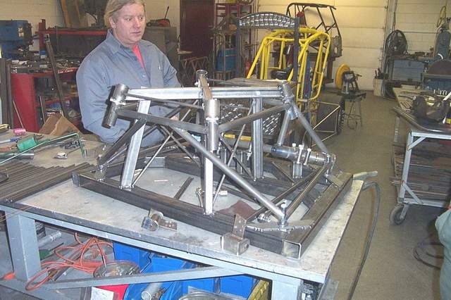
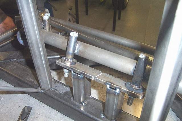

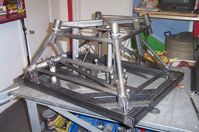
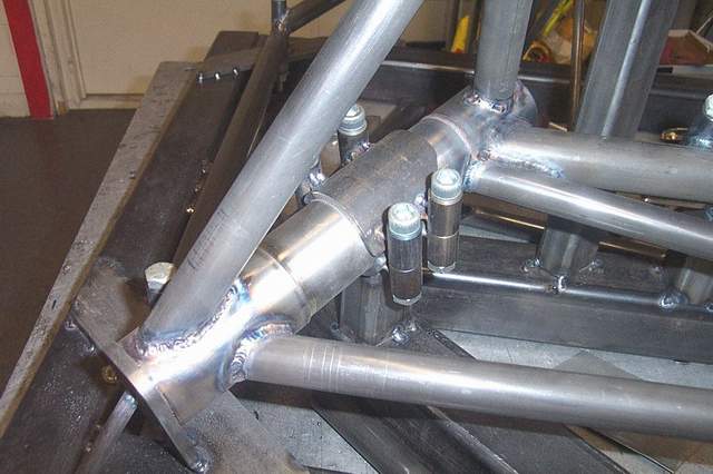
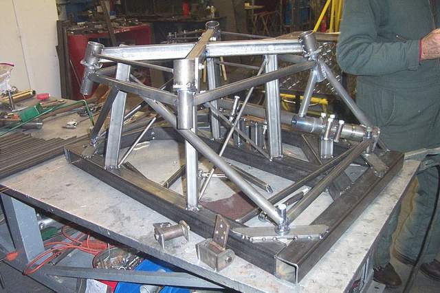
Jim Cash had this to say about the new mount:
Hey guys,
I thought the engine mount problem would create a lot of discussion, when word got out about the Indy mount. I have been weighing this for a month now, and would like to share my thoughts and reasoning with you.
Since my airplane was the first, I was pushing Mark hard, early on for a mount. The lack of one held me up for a couple of months, as matter of fact. That was the last part needed to complete my project. As a result, I came up with one of three bastard mounts that are similar to your production Mark l mount, but somewhat different. Several of us have up to a couple hundred hours on these mounts, and one has broken twice. None have collapsed causing major damage.
I immediately ordered an Indy mount after hearing about them, mainly because mine is different and could be harder to duplicate later as memory loss occurs. I don't intend to replace my existing mount right away. Instead, I want the Indy stashed in a corner if I need it. I may install it sometimes in the future during a hard cold winter.
Since word got around that I had ordered a new mount, I have received several inquires from builders trying to decide if they should order one. After a lot of thought, here is my answer and the reasons for it. The Indy mount is going to be available for the foreseeable future. If your kit has one of the new Mark ll Czech mounts, I would definitely not replace that one. That could prove to be an excellent compromise. If you have the Mark l, and are at the point in the building process where it is easy to install, I would definitely order the Indy mount. If you are like me with a finished airplane, the installation process is going to be pretty extensive. I am going to torque the nuts every time I remove the cowling, watch for cracks, and probably wait to install the new one when I need it. If I had the regular production run Mark l mount, I would not have ordered the Indy until it was needed.
There is no doubt that the strength of construction increases from Mark l---Mark ll---Indy. However, this is one of these areas where it is easy to overkill. So far, out of three breaks the F-1 has experienced, there has yet be any firewall damage or gear collapse, which speaks well of even the Mark l mount. It is too early to be sure which will prove to be best over the long term. Sometimes, no action is the right action. I have an engineering background also, and I can assure you that it is possible to overbuild a mount to the point where you start transferring stress from stronger point to weaker---finally to the firewall itself. When that happens your problems grow rapidly. I just finished helping a friend replace a firewall in a Piper Pacer, and that was interesting. Someone else made the point that this problem is not unique to the F-1. That's very true. Van and John Harmon have had similar problems. Art Chard was Van's first employee, built most of the RV prototypes, and he has many stories. Another thought that keeps reoccurring to me is that one person's definition of a good landing can be different than others.
Hope this helps a little. By the way, $800 is an excellent price for an engine mount of this type. Note Mark is passing them on to us at his cost, which is a great help. I personally did not expect him to take my old mount on any kind of exchange, because right now there is nothing wrong with it. These things take such a beating, that I kindly put them in the category as replaceable items anyway. I guess (at least in my case) I am buying $800 worth of "piece of mind".
Jim Cash, #10 *end of comment*
Return to the homepage: http://www.vincesrocket.com/
Last updated: 03/25/10
CAUTION: This web site is not a publication of, nor approved by, Harmon LLC, Team Rocket, Van's Aircraft or any other person or entity listed herein, except me. Be advised that I am a blithering idiot with neither brains nor money and my advice is not to be trusted. So there. You have been warned! Vince