Additions after 10-27-04
Most of the new stuff that I post is going on this page. However, I have recently added quite a bit of new stuff to the Pilot Reports page and several others. If you're interested, please check the other pages for updates once in awhile. Thanks, Vince
Matco brake, tire, & tube relationship

11-30-2007: Some tire inner tubes come with an extra nut and washer down near the base of the valve stem on the tube. If you've never seen those before, you're gonna wonder what they're for. Desser tire said to throw them away. Matco said to install them as shown. See the photo for details.
New tailwheel design
1-15-2007: The new tailwheel info has moved to this page: http://www.vincesrocket.com/products.htm
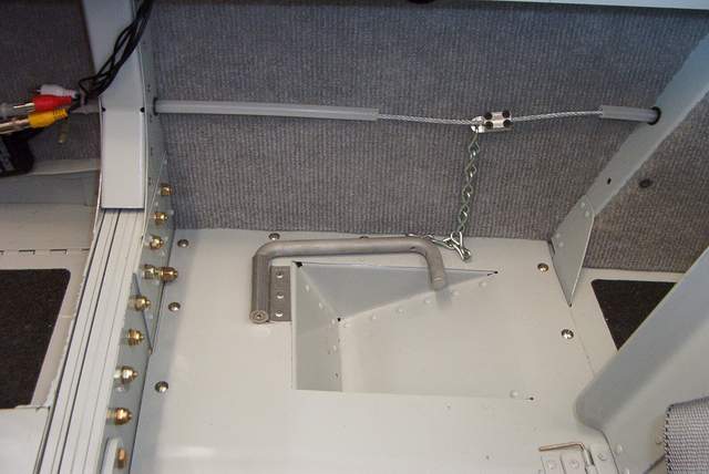
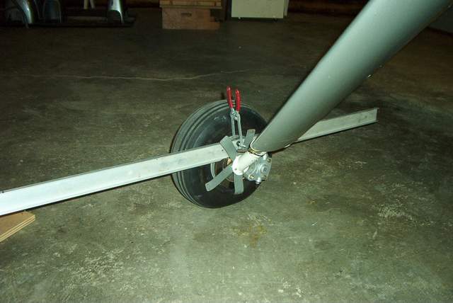
Tow bars
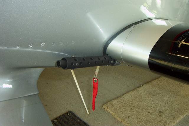
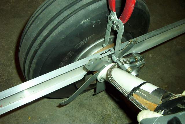
6-22-2007: The standard Cessna 150 towbar (ACS p/n 13-01800, $34) works fine with my tailwheels. Or you can roll your own for about $5. See below. It's made from ordinary electrical conduit. Just make sure that the conduit you buy will fit over the nut/bolt in your tailwheel, i.e. a little over 5/8" I.D. will work fine.
![]() Strap loose. Ready to install.
Strap loose. Ready to install.
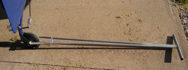 Strap tight. Ready to use. You could fly to Alaska and back and the tow
bar would still be attached.
Strap tight. Ready to use. You could fly to Alaska and back and the tow
bar would still be attached.
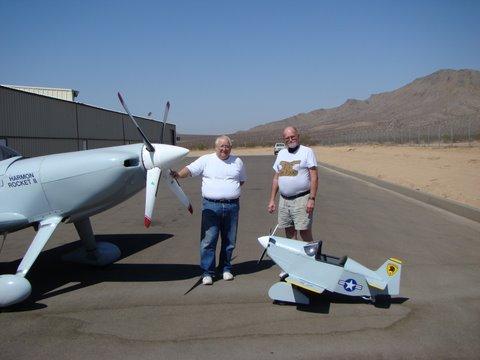
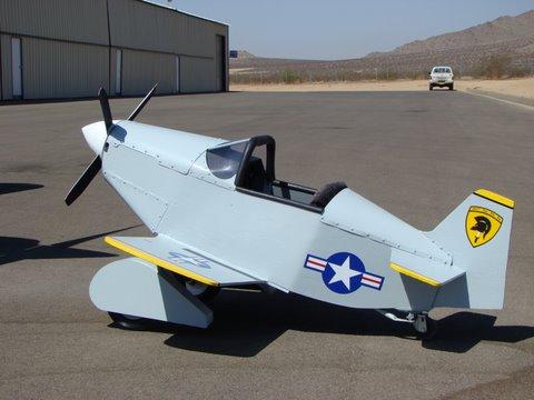
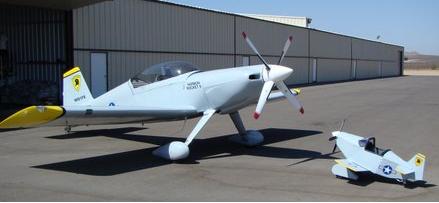
Tom Gummo built this sweet pedal plane Rocket to go with his full size HRII.
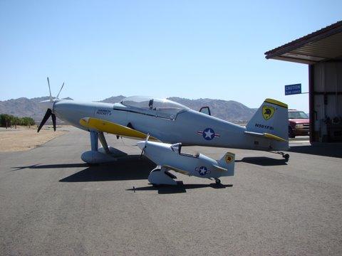
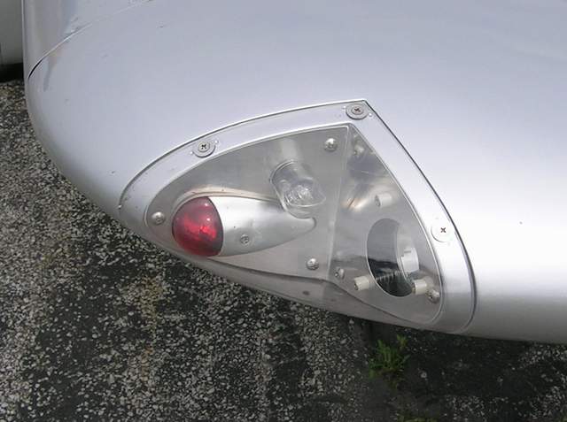
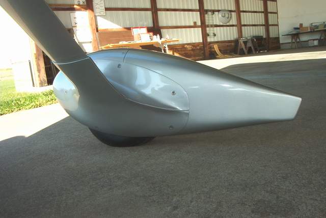
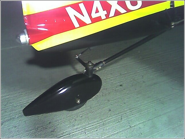 Paul Siegel added a sweet wheelpant to his new tailwheel.
Tow bars
6-22-2007: The standard Cessna 150 towbar (ACS p/n 13-01800, $34) works fine with the Rocket tailwheels. Or you can roll your own for about $5. See below. It's made from ordinary electrical conduit. Just make sure that the conduit you buy will fit over the nut/bolt in your tailwheel.
![]() Strap loose. Ready to install.
Strap loose. Ready to install.
Strap tight. Ready to use. You could fly to Alaska and back and the tow
bar would still be attached.
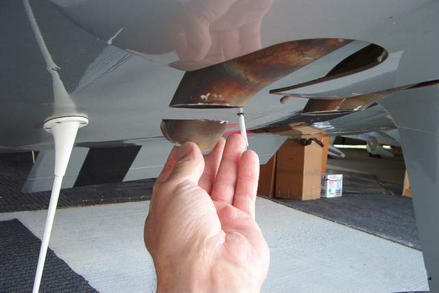
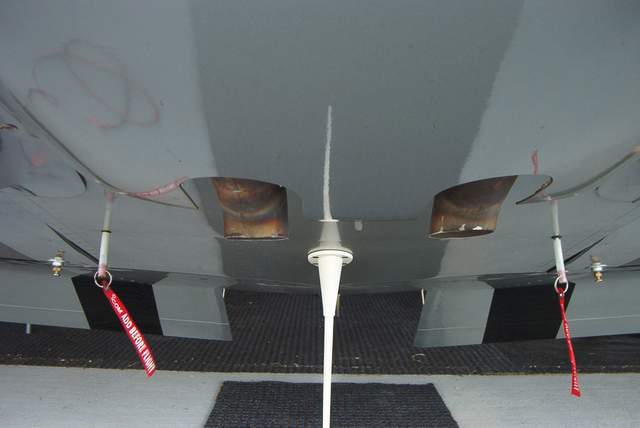
NACA vents versus wingroot vents
Update 1-5-2007: I've had enough time flying behind these wingroot vents now that I've drawn some ugly conclusions: cabin air taken from behind the engine is simply hotter than the air taken from under the wing. My OAT probe was originally in the NACA vents... and it read hot. Then I moved it to the wingroot vent... and it read hot. When I combine that info with what I can feel on my bare hand, I conclude that the fuselage mounted cabin air vents are always hotter than the underwing vent. YMMV, but if I ever build another RV or Rocket I plan to install 2 under wing scoops and 0 fuselage scoops.
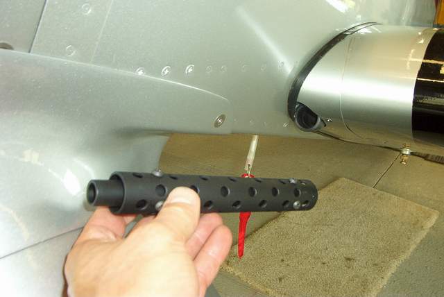 7-20-2006: Machine guns or clever birdproofing? You
decide.
7-20-2006: Machine guns or clever birdproofing? You
decide.
Seriously though, I had measured an 11 degree F difference between the air temps coming in from my fuselage side NACA vents (hot) and the NACA vent under the wing (cool). I can only surmise that the big prop is sucking some of the air out of the cowl when it passes. Or maybe the engine is simply hot enough to influence the air around the cowling. Who knows?
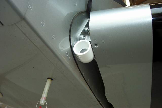
So, I did what others have done and installed a fresh air vent in each wing root. They provide plenty of airflow. The machine guns were made from scrap schedule 20 PVC pipe and are for ground use only... just for grins. HOWEVER, I am not convinced that the wingroot vents are significantly cooler than the standard NACA vents in the fuselage side, although I haven't measured them compared to the under wing vents.
The jury is still out for me. If I were building a new Rocket, I think I'd figure out a way to get ALL of my cockpit air from the underwing vents. Probably put one on each side.
When viewing the photos below, please keep in mind that this is a Harmon wing on an F-1 fuselage. If the fit of the wing to the fuselage looks really tight... IT IS! This area is much different than a standard F-1.
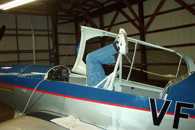
 Jeff Mear's folding rear seat pedals
http://www.airkitllc.com Another great Jim Wining's idea.
Jeff Mear's folding rear seat pedals
http://www.airkitllc.com Another great Jim Wining's idea.
Subject: Summer heating woes!
(Received from a friend out west )As the temps climb into the low 90's here my normal 195 oil temp has headed for 205, and the cylinders are running about 385 except number six which is 410. **** wanted me to try his "air ramps" in front of the 1 and 2 cylinders. I still think my air outlet under the back of the cowling is too tight. What do you think I should try first? What oil temp scares you? My oil temps are no problem in climb, but get hotter and hotter as the flight progresses. I left the oil dip stick loose on one flight and did notice the "backwards" air flow putting very small amounts of oil out on the front of the intake ducts.
I know, move to Alaska,
Cheers,
XXXXX
________________________________
From: Frazier, Vincent A
Sent: Wednesday, June 14, 2006 9:55 AM
To:
Subject: RE: Summer heating woes!
**** ,
I sure wish I had a few photos of what's under your cowling!! I suppose that these are the first things that I'd try (in order of easiest 1st)
1) turn off the electronic ignition advance and see if it affects the temps. Not sure if that is possible with your setup, but my Rose system could do that. The Rose system caused a large temp swing when it was on, towards higher CHTs. When running on a mag only, the EGTs went up (because the fuel was still burning as it left the cylinder.)
2) make sure that all air leaks are sealed. I used at least 2 tubes of red RTV around the baffles. Check the flexible baffle materials that seal to the top cowl, particularly around the case right behind the prop. I've seen HUGE air leaks there on many planes.
3) fly only when it's raining. Just kidding.
4) remove the upper gear intersection fairings (if you can safely fly without them holding your gear leg fairings in place) and see if you can shim the lower cowl air outlet open farther than it normally would be. I can do this on mine, but yours...???? Having the outlet propped open with a couple 5/8" spacers makes a measurable difference on mine.
5) have you removed the excess flashing that is found on many cylinder fins near the spark plugs? I'm told that it can cause higher temps. Refer to http://vincesrocket.com/Engine%20and%20Prop.htm . It's the first thing on the top of the page.
6) it's getting ugly now.... fly your plane to Hepler and leave it for at least 6 months while I test and rebuild the entire cooling system. Shouldn't cost more than $75,000 plus fuel for me to fly it everywhere between here and Florida. I can guarantee a temperature drop... but only during December.
7) you can add an airflow smoothing ramp around the engine mount tubes to help smooth the exiting air. It is easy to do, cheap, lightweight.... but may or may not help. It certainly won't hurt. Here is a photo of mine:
http://vincesrocket.com/2004-09-08/engine%20view%2014.jpg
8) balance your injectors and run LOP per Don Rivera at Airflow Performance. Guaranteed to lower your cruising temps.
9) install louvers on the lower cowl. I believe that this helped drop the temps on my plane by at least 20 degrees, but I would try everything else first. I don't really think that I needed the louvers since my temps were fine for the way I fly the plane, local conditions, etc. I just had to do it because I wanted to see what effect they would have! (Same reason that I shortened the gear legs!.... experimental is more fun)
10) what oil cooler are you using? Some claim that the SW is the best. My Positech (get the latest revision if you don't have it already) works fine. I'm sure that you've already hammered this area, but have a second look.
11) I'm beginning to think that our inlets aren't very efficient either. Lopresti must have some reason to make those ugly round inlets. Adding a set of those would really screw up your paint.
12) get one of the super duper ultra cowls that some guys are using. I have no data on them. You're on your own. I'll wager that one of these would screw up your paint and your wallet.
Good luck,
Vince
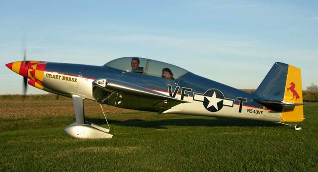
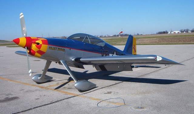
 6-2006: It's been awhile since I posted any new photos of my beautiful
Rocket. Here's a few taken in Louisville recently.
6-2006: It's been awhile since I posted any new photos of my beautiful
Rocket. Here's a few taken in Louisville recently.
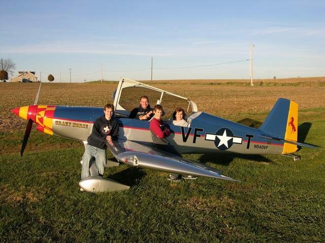
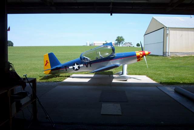 And one photo taken in front of my hangar. Sweet.
Main Gear Leg Shortening and Alignment Changes
4-3-2006
Background info: I built my Rocket per the F-1 plans as closely as I could in this area. I used an Indy engine mount. My plane weighs about 1225# empty. For purposes of alignment I had full fuel (42 gallons in my plane) and about 175# of ballast in the cockpit. I felt that this would represent a very typical load for this airplane.
As constructed, my plane had 2 1/2� of toe in per side and 4� of positive camber per side. The plane handled well and tracked just fine, but the tire wear was not very good as the outside half of the tread was nearly gone after 105 flight hours with mixed grass/pavement landings. The tires would squeak noticeably when rolling across smooth concrete due to the excessive toe-in.
Even though these airplanes are pussycats on the ground, I felt that there was still room for some improvements.
 I don't have a photo of the gear legs after the plane was finished, but I do
have this equivalent photo taken during construction with 1200# of sand in the
fuselage. It shows the 4� of positive camber nicely. 4� is too
much camber, IMHO. The excess camber causes an appreciable change in toe
in/out whenever the tail is raised during takeoff or lowered during landing.
It's not a control problem, but it is noticeable.
I don't have a photo of the gear legs after the plane was finished, but I do
have this equivalent photo taken during construction with 1200# of sand in the
fuselage. It shows the 4� of positive camber nicely. 4� is too
much camber, IMHO. The excess camber causes an appreciable change in toe
in/out whenever the tail is raised during takeoff or lowered during landing.
It's not a control problem, but it is noticeable.
 If you scrutinize this photo you'll see another (potential) problem area.
The titanium rod tapers until it gets to the bottom of the leg. Then it
suddenly becomes full size again just before it enters the axle socket. I
understand that the axle socket needs to have a sturdy attachment point, but
look closer. The relatively long axle socket and the wheel assembly put
about a 12" arm on the narrowest part of the gear leg. Yikes! Just look at
the photo, it really bends a lot in the lower 1/3 of the gear leg.
If you scrutinize this photo you'll see another (potential) problem area.
The titanium rod tapers until it gets to the bottom of the leg. Then it
suddenly becomes full size again just before it enters the axle socket. I
understand that the axle socket needs to have a sturdy attachment point, but
look closer. The relatively long axle socket and the wheel assembly put
about a 12" arm on the narrowest part of the gear leg. Yikes! Just look at
the photo, it really bends a lot in the lower 1/3 of the gear leg.
IMHO (and I'm not an engineer), the axle and wheel assembly are just plain putting too much unnecessary leverage on that narrow point on the gear leg. Later on, I'll explain just how much bending force I observed in this area. And it's just not necessary to put that much strain on that gear leg!
Last Spring (see below, under "5-25-05:") I did extensive testing with shims and decided that I didn't like putting a bolt into a crooked hole. However, the testing did show me that the tire wear should improve greatly if I could get rid of the excessive toe-in.
The Process:
Below is a process summary. Please read the entire text on this topic as I
put a bunch of comments below in the photo section. I will point out that
these changes require some work that isn't for the faint of heart. Cutting 2
1/2" off of an $800 gear leg is enough to make anyone stop to think. And having
a 1200# airplane up on jacks isn't exactly a feel good work environment either.
The text describes how I made changes to a finished and flying Rocket. If you're still building and can cheat by doing the gear leg and axle socket shortening now... do it! You can fix the axle socket by rewelding the pad on at about 45� and it should be very close to correct. Drill the socket to the leg to set the alignment AFTER you have the fuselage done and can add at least 1200# of weight to it!
1) Gather up the items you see in the photos below. You need chalk line,
wing jacks, levels, protractors, maybe a Sawzall, someone to do some simple
machine shop work, a welder, and other odds and ends.
2) Measure your current set up so you can make informed decisions about what to
change.
3) Jack the plane up and remove the axles. Mark the face of the axle pads
with a plumb line and a horizontal line. Mark them "left" and "right" and
"forward" to make it easier on yourself.
4) Using a machine shop milling machine if you have access to one, move the bolt hole EXACTLY 2 1/2" down the axle socket ( do NOT drill new holes in the gear leg unless you like useless holes). I'd recommend only drilling one side of the axle socket hole in the mill and drilling the other on the plane to match the existing hole in the gear leg which might not be exactly centered depending on how straight you drilled it the first time.
5) Cut off exactly 2 1/2" from the top of the axle socket. Saw it close and then use a lathe to finish to the exact dimension. Finish the inside radius to match the finished inside radius of part that you cut off.
A good way to double check your work here is to measure the dimension from the bolt hole to the top edge of the axle socket before you cut it off. The new bolt hole should be the same dimension from the new edge. These dimensions need to be spot on or your axle socket won't fit snugly against the gear leg as it should.
6) Saw up from the bottom of the axle socket until the axle pad is 90% free.
Leave a small amount of metal at the TOP CENTER so that the pad is still
connected.
7) This is the tricky part. Put the axle socket in a heavy vise that WILL
NOT MOVE and level the axle pad perfectly. Now using those measurements
that you took at the beginning, bend the axle pad as needed until your level
protractor shows the appropriate amount to correct for toe and camber.
8) Tack weld the pad. You'll probably have about 3/16" to fill at the bottom where you opened up the slot. Put a heavy tack (so it won't break when you put the airplane's full weight on it) but DON'T finish the weld. You'll probably have to do this process at least twice! Maybe three or four times!!!!
9) Put the sockets back on the plane and reinstall the axles and wheels.
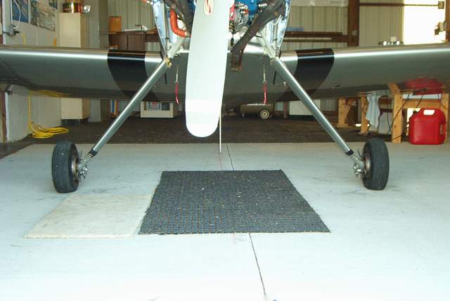
10) Carefully lower the tires onto some GREASED PLATES so that the alignment can self adjust itself as the gear spreads apart. Be careful. I had a tack weld break and a tire went flying.
9) Take more measurements to see what needs to be adjusted. I made mine to 0� toe and 0� camber at the weight mentioned above.
11) If necessary, cut the tack welds and go back to step 5 and readjust the axle pad as needed using the new measurements.
12) When you're satisfied with the new alignment, finish weld the axle sockets and reinstall.
Getting to work: The following text and photos attempt to describe what I did and why I did it in even more detail.
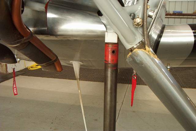
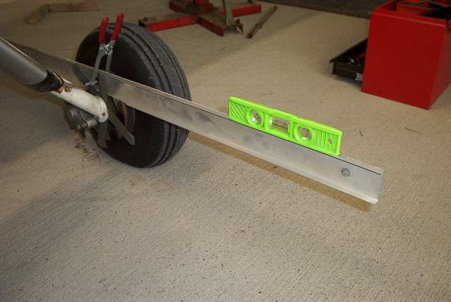 Before you cut anything up, take some measurements. Use a long piece of
straight channel clamped to the brake disc to check the toe in/out versus the
centerline of the plane. WHAT? You didn't make a permanent mark on the
centerline of your firewall! Well, neither did I, but it's easy to find by
measuring between the lower outboard EM bolts at the bottom longerons.
Then drop a plumb line to the floor. A chalk line tied to the tailwheel
axle and stretched to the nose will complete your shop floor geometry lesson.
Before you cut anything up, take some measurements. Use a long piece of
straight channel clamped to the brake disc to check the toe in/out versus the
centerline of the plane. WHAT? You didn't make a permanent mark on the
centerline of your firewall! Well, neither did I, but it's easy to find by
measuring between the lower outboard EM bolts at the bottom longerons.
Then drop a plumb line to the floor. A chalk line tied to the tailwheel
axle and stretched to the nose will complete your shop floor geometry lesson.
 Level the channel and drop a line to the floor at the front and rear of the
channel.
Level the channel and drop a line to the floor at the front and rear of the
channel.
 Measure over to the centerline. A little trigonometry will tell you the
degrees (2 1/2� of toe in per side on mine), but ultimately all we really need
to do is make the front and back to be identical. If you did all of your
layout correctly, your measurements will be the same on each side of the plane.
Keep this technique in mind as you'll be doing it several times before this job
is done. Also keep in mind that when you jack the plane up your centerline
is likely to move as the plane sways around. You'll have to double and
triple check the centerline.
Measure over to the centerline. A little trigonometry will tell you the
degrees (2 1/2� of toe in per side on mine), but ultimately all we really need
to do is make the front and back to be identical. If you did all of your
layout correctly, your measurements will be the same on each side of the plane.
Keep this technique in mind as you'll be doing it several times before this job
is done. Also keep in mind that when you jack the plane up your centerline
is likely to move as the plane sways around. You'll have to double and
triple check the centerline.
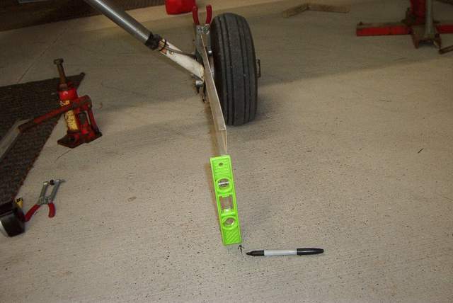
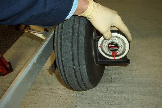 Measure the camber before you start jacking the plane up. It reads 4� of
positive camber on mine. You can use the brake disc or the outboard edge
of the wheel, but not the tire since it's fatter at the bottom!
Measure the camber before you start jacking the plane up. It reads 4� of
positive camber on mine. You can use the brake disc or the outboard edge
of the wheel, but not the tire since it's fatter at the bottom!
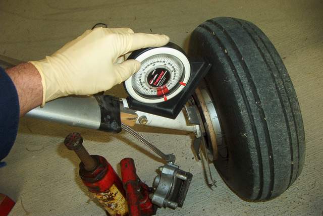 Heck, measure it here also. Mine was about 45�. Hmmm, add 45� to 4�
and get 49�. This is pretty close to the 50� angle that I eyeballed
using a protractor in my shop right before I took the axle sockets to the band
saw for a torture session.
Heck, measure it here also. Mine was about 45�. Hmmm, add 45� to 4�
and get 49�. This is pretty close to the 50� angle that I eyeballed
using a protractor in my shop right before I took the axle sockets to the band
saw for a torture session.
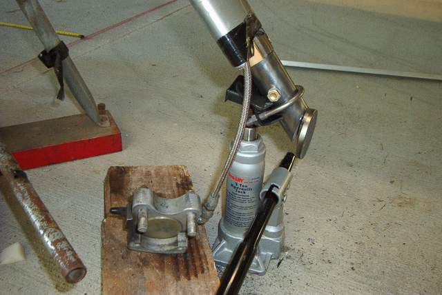 I didn't really need this jack, I just put it here to show how you might jack
this thing up if you were simply changing a tire. The jack pad is a simple
weldment made from a 1 1/2" muffler clamp and a few steel scraps. Also
shown in this photo is the axle pad which is 90% cut off so that it can be bent
and adjusted as needed.
I didn't really need this jack, I just put it here to show how you might jack
this thing up if you were simply changing a tire. The jack pad is a simple
weldment made from a 1 1/2" muffler clamp and a few steel scraps. Also
shown in this photo is the axle pad which is 90% cut off so that it can be bent
and adjusted as needed.
So, you're wondering "Why didn't he just use these jacks?" Well, there's no way to get the axle socket off without setting the plane on the concrete. But I did learn something that I thought was very interesting and it relates to the taper on the gear leg and the stress concentration that I speculated about above.
I had it in my mind that I'd jack the plane up on these jacks and simply bend the axle pad (it was loose due to cutting through 90% of the weld) as needed until the pad was plumb and toe was 0�. Seems logical. I mean just how much could having the axles and wheels installed change that angle? Not much.... right? WRONG! I tried this and found that the increase in bending arm that occurred when the wheels were installed was a hefty 3 1/2�. Well, well, since I was trying to correct a 4� camber that 3 1/2� seemed a little too huge.
It would seem by a little simple math that if the camber was 4� and we got 3 1/2� just by moving the fulcrum around, then maybe just shortening the gear leg would correct the camber. Well, it's a nice thought but just shortening the gear leg causes the camber to go the wrong direction. Doh!
So, it seems to me that the arm of the axle and wheel assembly is really putting some stress on that narrow part of the gear leg. Will it hurt anything? Don't ask me. OTOH, I do feel better knowing that I reduced that stress concentration on my gear legs.
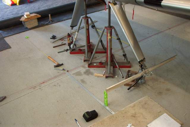
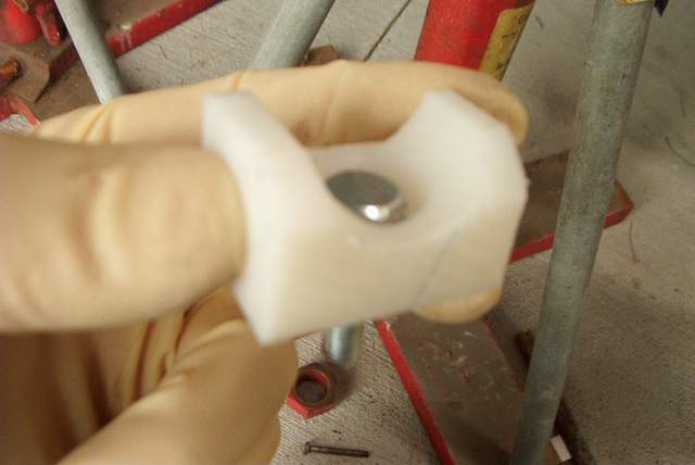 The main jacking was done with these wing jacks and an adapter pad that I made
from a scrap of nylon block. A block of nylon, a few spade bits, and a
band saw are all you need to whip one of these out and it will make it safer to
jack the plane up. The nylon didn't even scratch the paint. Make
sure that whatever you use to jack the plane up is safe.
The main jacking was done with these wing jacks and an adapter pad that I made
from a scrap of nylon block. A block of nylon, a few spade bits, and a
band saw are all you need to whip one of these out and it will make it safer to
jack the plane up. The nylon didn't even scratch the paint. Make
sure that whatever you use to jack the plane up is safe.
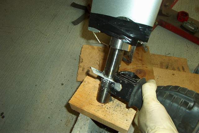 Cutting the gear leg off with a Sawzall. Crude, yet totally primitive.
It will work however. I couldn't easily remove the gear legs, and
didn't want to remove them considering that it took about 75 hours for them to
fully seat in the EM sockets, so the Sawzall did the job. It would have
been a helluva lot easier to do during construction though! If you use a
Sawzall on yours, measure carefully and bring several blades and some cutting
oil to help the process. I'm told that titanium will work harden.
FWIW, I knocked the teeth off 4 bimetal blades before I got mine cut off.
Cutting the gear leg off with a Sawzall. Crude, yet totally primitive.
It will work however. I couldn't easily remove the gear legs, and
didn't want to remove them considering that it took about 75 hours for them to
fully seat in the EM sockets, so the Sawzall did the job. It would have
been a helluva lot easier to do during construction though! If you use a
Sawzall on yours, measure carefully and bring several blades and some cutting
oil to help the process. I'm told that titanium will work harden.
FWIW, I knocked the teeth off 4 bimetal blades before I got mine cut off.
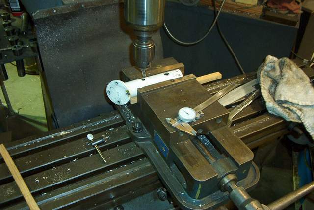 Moving the bolt hole with a milling machine should result in a perfect fit
later. Like I mentioned earlier, I didn't drill both sides of the hole,
preferring to finish the drilling on the plane in case the hole in the gear leg
isn't exactly centered.
Moving the bolt hole with a milling machine should result in a perfect fit
later. Like I mentioned earlier, I didn't drill both sides of the hole,
preferring to finish the drilling on the plane in case the hole in the gear leg
isn't exactly centered.
 Measuring the axle pad prior to tack welding. The tube is level and the
protractor read about 50� in the original configuration.
Measuring the axle pad prior to tack welding. The tube is level and the
protractor read about 50� in the original configuration.
I used a propane torch and a scraper to remove that #$%^& ing powder coating. IMHO, powder coating has no place on an airplane's structural parts. And now my airplane has NONE.
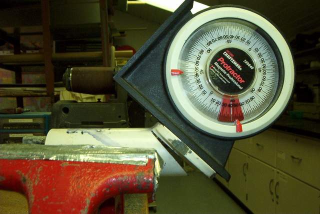
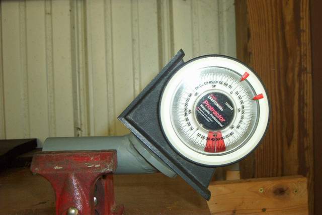 Measuring the final pad angle which was about 45�
On my first attempt at tack welding the pads back in place after changing the toe and camber, the tacks broke as I lowered the plane to check the work. The spring gear sent a wheel flying across the hangar as the plane tilted slightly back onto the jacks. I was glad that my 'nads weren't in the way. The next tack welds I made were much bigger.
I required 2 tries to get the pads (alignment) right. Jim Wining said that he took 5 tries to get his welded where he wanted them� but I had the advantage of having his expert advice to guide me!
Weight lost by trimming the parts: about 750g or 1.65 pounds according to the pile of steel and titanium laying on my bench.
Most visible change: the nose is about 1 1/2" lower which quite surprisingly changes the way that the plane looks as you walk up to it. I can ALMOST see into the oil door now� but not quite. Visibility over the nose during taxiing is slightly improved also.
The spinner height measured 63 3/16" prior to this work and 61 3/4" afterwards.
Most handy improvement: I can roll the plane around like it was on ball bearings now. Very much less effort is required to move the plane around. It's even noticeable while taxiing. It just rolls easier.
TOL's: I made 3 grass TOL's and 3 hard surface TOL's yesterday. If you saw the weather yesterday in Indiana you know that the wind was pretty fierce, gusting enough to weathervane the tail while parked on the ramp, so the new gear got a good workout in the quartering crosswinds.
The takeoffs and taxiing were well behaved, nothing to indicate any directional control problems. The shorter gear also moves the wheels very slightly more forward, definitely an OK change in my opinion. I made no attempt to measure how far the wheels moved forward.
The shortened gear is noticeably stiffer (as you'd expect) and my first landing gave me a nice bounce (I was testing the welds) but nothing unusual given the gusty winds. The stiffer gear seems to eliminate the "floppiness" of the old gear.
In spite of the winds, or maybe because of them, I horsed around a bit on the hard surface, holding the tail up on roll out and jabbing the rudders to see what she'd do. She behaved just fine. Probably the most noticeable thing to me, as I mentioned before, was that the plane just wanted to keep rolling. I wouldn't have guessed that the rolling friction change would have been so noticeable.
6 TOL's isn't a big enough sample for me to sing the praises of these modifications, but I certainly didn't find any bad habits tot concern me yesterday. More on that later after I fly it more.
There is much more to consider here before anyone runs out in the shop to chop their legs off. I think I spent at least six months thinking about doing this before I was convinced that I should make the changes.
 Here's a shot of the finished gear. You can easily see the camber change.
4-5-06: Here's a thread regarding why I didn't simply use shims to correct the alignment.
Vince,
Glad you finally made this mod--I've been holding off in this area until you
finished, and it sounds like it is worth doing. Three questions:
1) Instead of cutting and rewelding the axle pad, why not just machine
an adapter plate to mount on the pad?
You're talking about using a shim. You can buy those. They're ridiculously
expensive considering that they're a simple wedge of metal. The 1/2� shims are
$37 each in ACS catalog. Do the math to figure out how much that would
cost you!
I shimmed the axles last May to test how I'd like the gear without any camber
and toe-in. The tests were fine. What wasn't fine was putting a wedge (the shim)
between the axle and the axle pad. There is NO way install the shim without
having the axle bolts going into a crooked hole. IOW, when you tighten the 4
bolts that hold the axle on, the bolts get bent. Bent bolts are weakened bolts
regardless of how many Cessnas are flying around with this same situation. Not
for me, but it is technically OK to have a small shim in there.
OTOH, I don't think that it would be OK to put a large shim stack in there to
correct for 4� of camber AND 2.5� of toe. That would be a huge stack of shims
and the bolts holding it would be under severe strain� if you could even get
them in without breaking them.
When I tested shims last May, I only tried to get rid of the camber or the toe,
not both at once.
I'm sure that there are other ways to machine an adapter or make a new axle, but
they would be as much work as simply correcting the axle socket.
2) I guess it could cause problems if you've already done
all your fiberglass work, but other than that why not?
Yes there are fiberglass problems. After you make the changes that I did, the
old intersection fairings are junk. It's time to make new ones. That will be
next week when the weather is warmer.
3) And as to the point about it being much easier to roll
now, I assume that is because you are now running 0� toe in, and not the 2.5�as
before? I don't see shortening the gear leg helping in this area (unless I've
missed something--which won't be the first time).
No, the shortening doesn't change the rolling qualities. But the 2.5� toe in per side (5� total) certainly does! 5� is a LOT of misalignment! And it sure wears the tires out quickly.
Vince
Thx, Vince. As usual, you're the man! And you've explained why the shims won't
work--now, do I trust my welding skills....?
Paul
Paul,
I wouldn't worry too much about the welds... unless they're really bad. The
weakest link in this chain is the 4 bolts that hold the axle on. Those things
are amazingly small.
Have fun! Vince
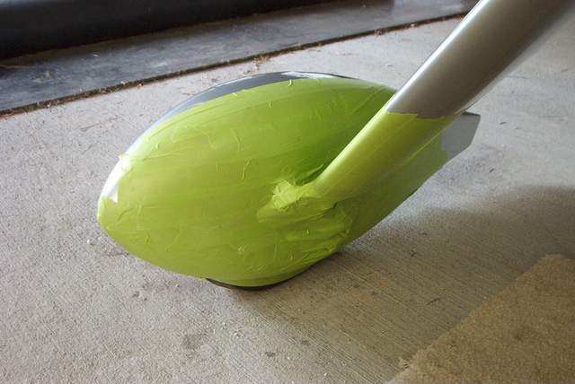
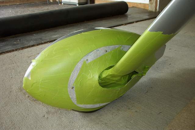


 I had to fix the LGIFs after shortening the gear. They would not fit.
Rather than make completely new fairings and try to hit the old nutplates in the
wheelpants, I cut off the part that wouldn't fit and added new glass.
I had to fix the LGIFs after shortening the gear. They would not fit.
Rather than make completely new fairings and try to hit the old nutplates in the
wheelpants, I cut off the part that wouldn't fit and added new glass.
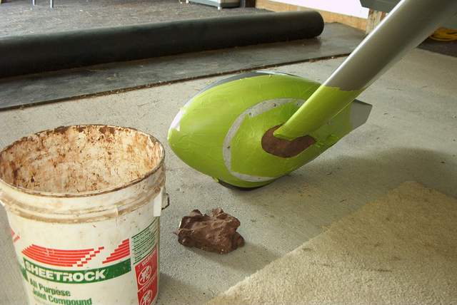
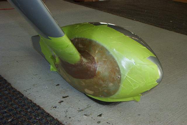
The sequence is as follows: 1) tape over the wheelpant 2) install the trimmed LGIF and tape over the parts that you don't want clay to stick to 3) fill the gaps with clay 4) smooth it to an aerodynamic perfection 5) not shown in the photos is where I removed the green tape from the LGIF after the clay was in place 6) glass it 7) also not shown is the trimming and painting.
Additional comments July 2006: Now that I've got lots of TOL's on the short gear, here's what I like and what I don't:
Likes: better vis over the nose and the 0/0 alignment is perfect. It's definitely a GOOD thing to WAIT until you can set the gear socket alignment to 0 toe and 0 camber with weight on the wheels.
Dislikes: the shorter gear is a little too stiff for my tastes now. I'm not going to change it back, but I don't think I'd recommend that a new airplane have the gear shortened before flying it first. Tom Martin reports that the short gear is not optimal on his EVO.
Worthless Trivia
3-2-2006: IIRC, our Hartzell 2 blade props are 80" in diameter. So, 2πR = 251" x 2700RPM = 678584"/minute � 12 = 56549'/minute � 5280 = 10.7 miles/minute X 60 = 643 miles per hour propeller tip speed.
Hmmmmm, worthless trivia.
The never ending quest to find stupid things to spend money on
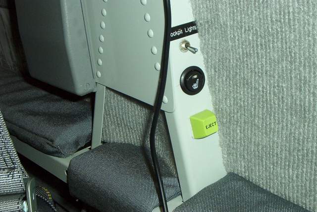
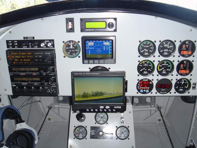
 1-10-2006: Rear seat passengers sometimes complain
because they can't see the instrument panel in the Rocket very well. If
they're short, they can't see it at all. Rather than listen to the
continual whining coming from the backseat, I installed an LCD video screen and
camera. These items were left over from the FLIR system described below.
1-10-2006: Rear seat passengers sometimes complain
because they can't see the instrument panel in the Rocket very well. If
they're short, they can't see it at all. Rather than listen to the
continual whining coming from the backseat, I installed an LCD video screen and
camera. These items were left over from the FLIR system described below.
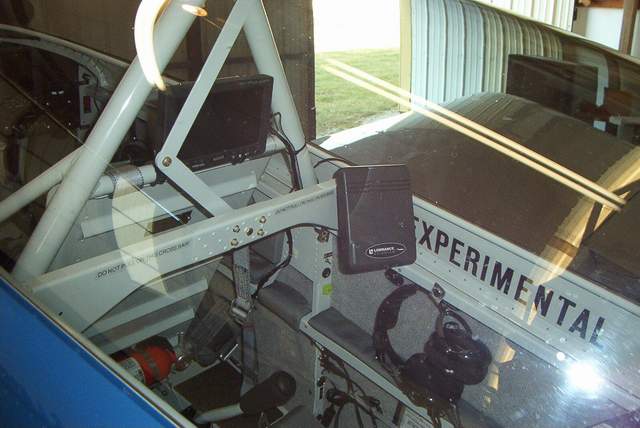
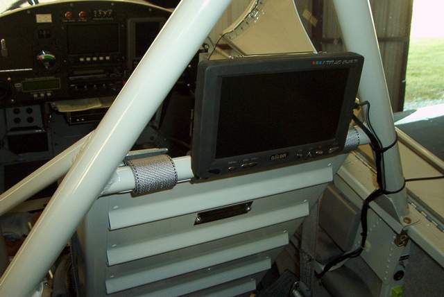
The video screen mounts very nicely between the rollbar tubes with a couple Adel clamps. That's a Lowrance GPS mounted to the right of the LCD screen on the canopy frame. Now the backseaters can navigate and monitor the instrument panel. Next they'll want rudder pedals and a throttle. Sheesh.
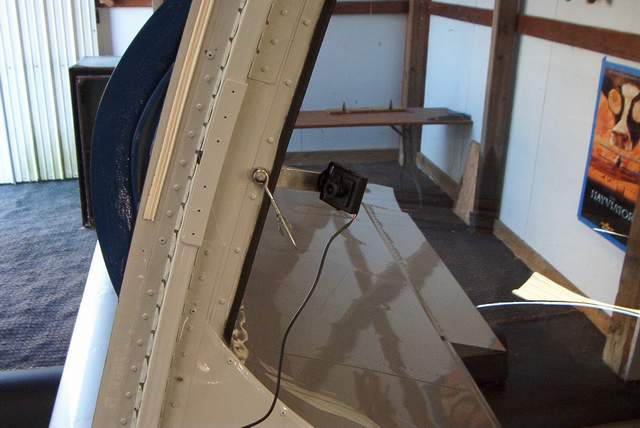
 The camera is temporarily mounted on the canopy frame with a scrap of aluminum.
The camera is mounted just above my line of sight to the panel. Somewhere
I have a scrap of lightweight gooseneck lamp tubing that I'd like to mount the
camera on. That way it can be easily swung aside if needed.
The camera is temporarily mounted on the canopy frame with a scrap of aluminum.
The camera is mounted just above my line of sight to the panel. Somewhere
I have a scrap of lightweight gooseneck lamp tubing that I'd like to mount the
camera on. That way it can be easily swung aside if needed.
The only drawback that I can see to this system is that the camera being mounted at a slight angle distorts the image somewhat. Nonetheless, the data on the GRT EFIS is easily read on the rear LCD screen. Cool.
 11-2005: A typical day of flying makes the monsters
hungry for 100LL.
11-2005: A typical day of flying makes the monsters
hungry for 100LL.
 11-20-05: I added some new equipment to the rear
cockpit.
11-20-05: I added some new equipment to the rear
cockpit.

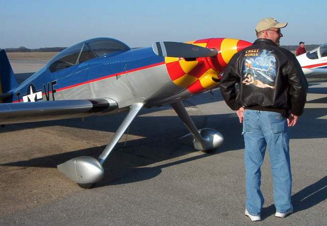 11-16-05: Here's a photo of
the back of my new flight jacket made by RT Foster, who you see at Oshkosh in
the fly market every year. Needless to say, that's an artistic rendition of my
wife at the bottom. Hubba, hubba! I didn't say it was an accurate
rendition... but it's not too far off. ;-)
11-16-05: Here's a photo of
the back of my new flight jacket made by RT Foster, who you see at Oshkosh in
the fly market every year. Needless to say, that's an artistic rendition of my
wife at the bottom. Hubba, hubba! I didn't say it was an accurate
rendition... but it's not too far off. ;-)
Sure, it's pricey but you should have heard my 15 year old son, Blake, making barf noises and gagging when he saw it. Totally worth it. Sure, he'll need years of therapy later, but it'll make him a better man.
http://www.rtfosterart.com/ Check out the other art by RT. No, I don't get a kickback... I just like their work!
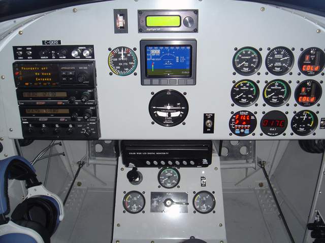
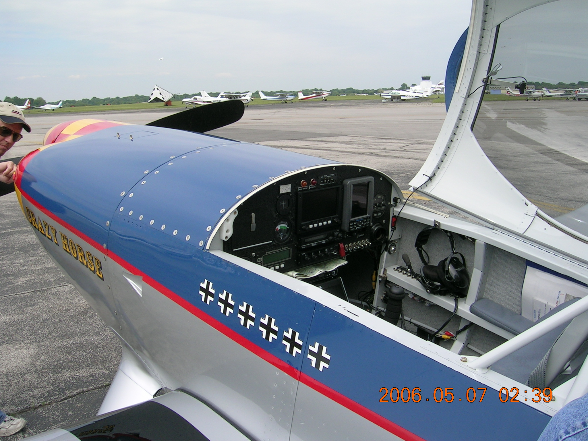
 Fall 2005: Mark Esterhuizen's panel with pop up FLIR.
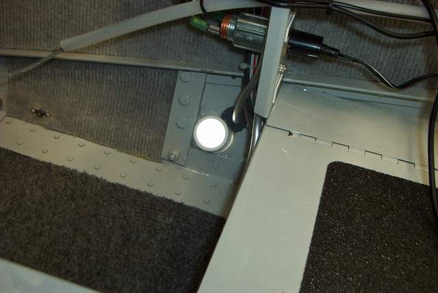
Mark Esterhuizen and I have been experimenting with some FLIR equipment. FLIR is "Forward Looking Information System" and consists of a Sony bullet camera mounted either in the left cooling inlet (mine) or in the wheelpant (Mark's).
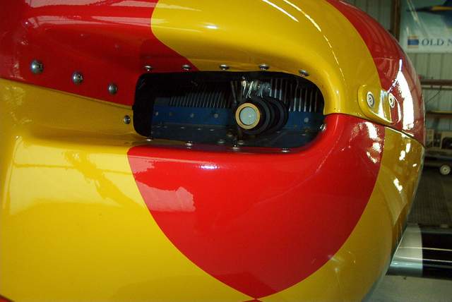 I
installed a camera in the left inlet. The camera feeds the image to an LCD
screen under the panel. I really like it and find it to be extremely
handy. I've used it for about 30 hours now (3/2/2006) and find it to be
extremely handy.
I
installed a camera in the left inlet. The camera feeds the image to an LCD
screen under the panel. I really like it and find it to be extremely
handy. I've used it for about 30 hours now (3/2/2006) and find it to be
extremely handy.
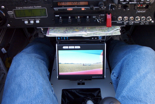

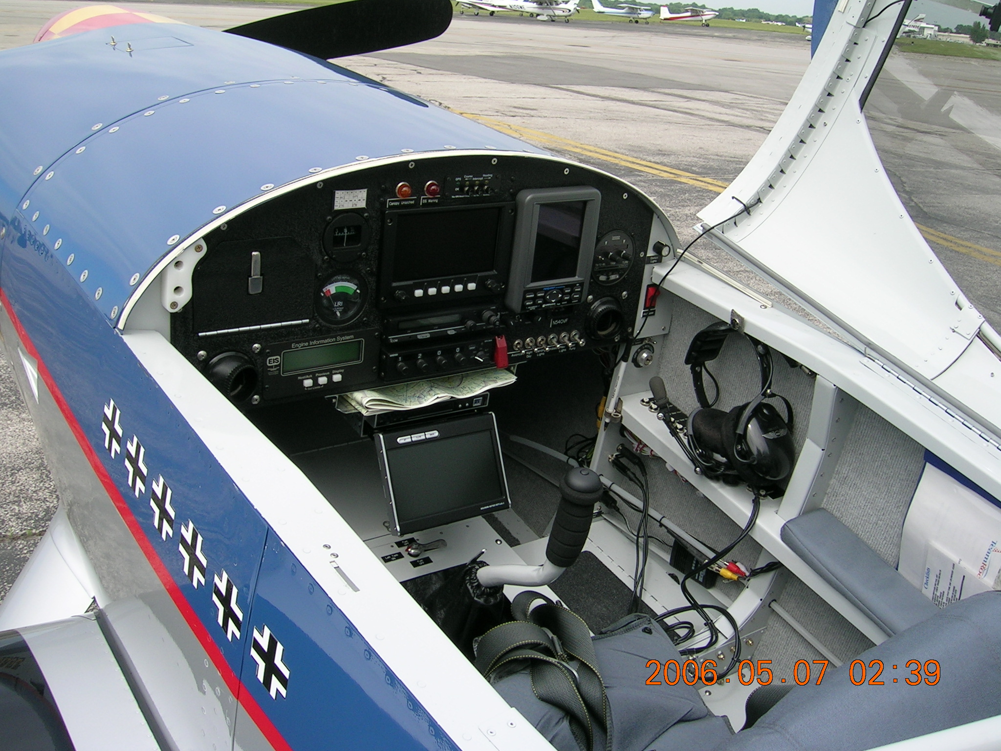
 My panel with pop up FLIR. In photo #1 and #2 you can clearly see the RV-6
that is taxiing in front of me about 100 feet away. In photo #3 you can
see that I can't see him whatsoever.
My panel with pop up FLIR. In photo #1 and #2 you can clearly see the RV-6
that is taxiing in front of me about 100 feet away. In photo #3 you can
see that I can't see him whatsoever.
I installed my camera/video system mostly so I could keep up with my nose dragging friends on the taxiways. Used properly, it eliminates the need to do S-turns. Yeah, you still gotta keep your eyes open, but having an extra "electronic" eye that can see directly ahead is really nice.
The biggest problem is finding a sunlight viewable LCD screen. The previous two screens that I tried were a bit weak in the sunlight, although they were still useful. The pop-out screen that I have now is almost too bright and washes out the image a bit too much. But the pop out feature is handy since it takes up less space. Overall, I am very pleased with it.
More later... the experiments continue.
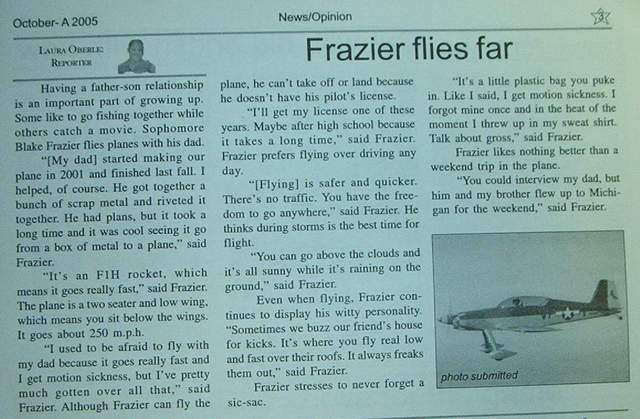 11-09-05: Check this out� my son, Blake, was interviewed by the
high school newspaper for an article about my plane.
11-09-05: Check this out� my son, Blake, was interviewed by the
high school newspaper for an article about my plane.
I think that the only thing in the entire article that is accurate or true is that my son, Blake, did indeed get sick in an RV-6 and barf in his shirt. Vince
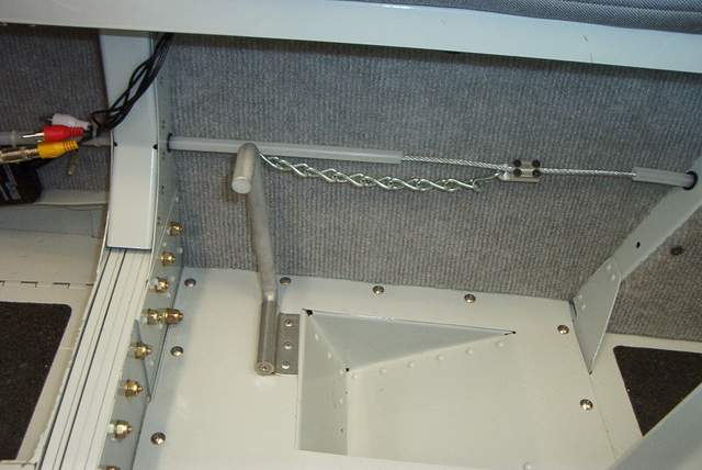
9-1-05: Jim Winings had a good idea on how to make the stick forces lighter by modifying the bellcrank at F408. Randy, Jim, and Bob assured me that I would like it. So I installed one.
Yes, it's installed now and I like it�.but the installation�..GACK! Read on.
Jim told me that the bellcrank only needed to be shortened by 7/8" at the top pivot. Easy enough, I thought, although I knew that I would likely need to readjust the other rod ends in the system� which means possibly removing a few floorboards.
 Plan on taking out a few floorboards.
I made the bellcrank in about 30 minutes. Easy stuff. The next day I went to the airport to install it. It was about 95 degrees OAT so I took a fan. That was a good thing because I'd use it for the next 4 trips to the airport.
I installed the new bellcrank and immediately saw that the rear elevator pushtube wasn't long enough anymore. No problem, just lengthen the rod ends. Doh! Still not enough. OK, order longer rod ends. The longer rod ends are $45 each. #$&&*! No thank you! OK, just change the throw of the bellcrank. Dang it! That made the forward pushrod inside the control stick torque tube smack the top of the torque tube. Time to give this some serious thought.
I really wanted to quit right there, but I trust Jim's opinion on these things and I already was tired of the heavy elevator feel, particularly during slow flight. So I kept thinking.
I came up with a slightly banana shaped bellcrank. The top pivot is moved aft about 3/8 or 1/2" to accommodate the short rear pushtube and allow the forward pushtube enough clearance to not hit the top of the control stick torque tube. OK, now things were looking up a bit.
Next I found that the increased stick travel caused the front stick to hit the panel and the rear stick to hit the front seatback. DOH! OK, I'll adjust the rod ends� nope, not enough travel there. OK, bend the sticks. That worked�. after I cut and rewelded (and repainted) the front stick. The rear stick just got more bend� screw the paint. I don't sit back there anyway.
Things were really coming together now�. and I'd only lost 5 gallons of sweat. Yuck. I hate summer in SW Indiana. Anyway, the controls worked as desired with no interferences. Time to reinstall the floorboards and stick boots. (You know what is going to happen next, don't you?)
@#$# !!! Now, the rear seat floorboard stiffeners scrape on the top of the middle pushtube. A belt sander made short work of that snafu. I don't need those full sized stiffeners anyway because my pax sits on an aluminum seat pan that doesn't touch that area of the floor. (There's a caveat for those who aren't using a seat pan back there. Using only a cushion would put all the pax's butt weight right on top of the floorboard that can bow and scrape on that tube. I think that could be an overlooked problem area for many Rockets and tandem RVs.)
So, I put the front stick boot back in position and screwed her down. #$*&*(&!!! Now the front stick scrapes the edge of the boot! Will this never end? I took the cover home and ripped out the old, too-small boot. I made the formerly round stick hole a nice big square hole. Then I whipped out the sewing machine and stitched up a very nice custom boot. Actually, the new boot is much, much nicer than the store bought one that was there before. The old one had a nasty hole slashed in it for the aileron manual trim lever.
Finally, it's all back together. In the silence of the closed hangar I can move the controls to all points and hear nary a scrape or clunk anywhere. Only my gnashing teeth can be heard.
And inflight, the elevators are much lighter with more stick throw. I like that.
Regardless, if you mod that bellcrank, you'd better not be fat. The extra travel puts the stick well into my belly on landing. On the bright side, now I can pleasure myself (whether I want to or not) during crosswind landings. ;-) So, if you're bubba size, you might want to give this mod some serious thought before you put it in.
Summary: I only moved ONE bolt by a measly 7/8" and it took 4 days. This is a clear example of why ANY modification puts your building schedule WAAAYY behind. However, if you're going to make this mod, for goodness sake do it during construction, not after you're at the airport.
Vince
P.S. Please remember that my Rocket is a combination of Harmon and F-1 parts and your F-1 may be slightly different from mine in many places.
 8-26-05: I was
surfing the web and found test instructions for the little Transpo F7078 voltage
regulator that I used. I hope I never need them.
8-26-05: I was
surfing the web and found test instructions for the little Transpo F7078 voltage
regulator that I used. I hope I never need them.
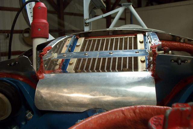
8-21-05: I have been taking engine temperature data all summer long. Overall, the performance of my cooling system has been good, but there are always areas of concern. On the hottest days, 95 degree F, the cooling system can't quite cope with powers above 21MP/2300RPM. Oil temps get up to 215F and CHTs climb past 400. Yes, I know that those numbers aren't bad, but they could be if I wanted to run at higher power settings.
With some help from John Crabtree, I installed an old ASI in the cockpit. Lines were run into the engine compartment and readings were taken. An article in Sport Aviation (1996 IIRC) describes how to interpret the data gathered. This data seemed to indicate that my plane needed more outlet area.
Shimming the outlet open with some spacers was done and another flight was made. Temps were improved somewhat. I decided that I'd go ahead and install a set of the louvers that Billy Waters sells. Email address for Billy Waters is Jones15183@aol.com
After installing the louvers, the CHT temps dropped markedly. Maybe as much as 40 degrees.
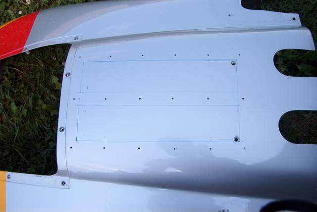 Louver layout and preliminary drilling. I used a cutoff wheel to open up
the hole. I was a shame to cut a hole in such a nicely painted part.
Louver layout and preliminary drilling. I used a cutoff wheel to open up
the hole. I was a shame to cut a hole in such a nicely painted part.
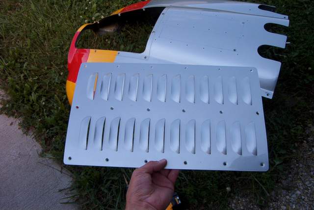 Louver ready to install. Some mild bending was required.
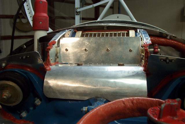
 Hmmm, looks OK to me. Sorta like a '29 Ford. Oh well, that matches
the engine technology anyway.
Hmmm, looks OK to me. Sorta like a '29 Ford. Oh well, that matches
the engine technology anyway.
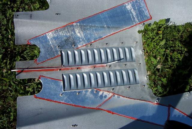 Inside the cowl. I need to add a little red RTV around the perimeter of
the louver.
Inside the cowl. I need to add a little red RTV around the perimeter of
the louver.
More later.
9-26-05: I hesitate to post anything because I don't have any speed data, but temp data� yeah, plenty of that.
I put louvers on the lower cowl. As expected, they do lower cruise temps. CHTs went down by 40 F and oil temps are always at or below 190 F and are easily managed with the oil cooler door.
The effect of the louvers during climb is helpful, but the temps don't drop as much as during a nice stable cruise (as expected). CHT temps probably peak 20 lower than before during climb. Oil never gets hot during climbs.
Overall, they did what I expected, perhaps too well. I saw a big drop in CHT temps� now the CHTs are too cool. I can see no difference in cruise powers or speeds, but I haven't done anything to speak of to confirm any of that.
1-10-2006: For cooler seasons, I added a simple internal sliding door, ground adjustable only. Keep it simple. I'll post pictures of it someday... if I ever have the camera on hand while the cowling is off of the plane.
Is it better than a cowl flap, undoubtedly not, but is it simpler and easy to install, undoubtedly yes. Did I really need it� um, probably not on anything but the very hottest days.
Operationally though, it is dirt simple. This winter I have flown with the louvers completely closed with the sliding doors. CHT temps hover around 300 to 320. When the weather warms up again I'll simply remove the sliding doors. I also have a set of partial doors in case I want to tweak the cooling flow later. Later, Vince
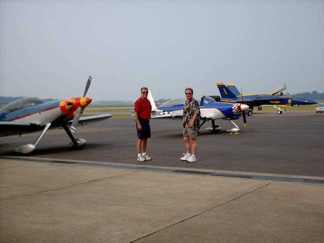 6-26-05: Jim Truitt and I were at the Evansville
airport during the "Thunder on the Ohio" airshow and boat races.
Here you can see us after giving the Blue Angel pilots a briefing on how to
..... um, .... er, ... actually I don't think there is anything that I can teach
those guys.... well, maybe if one of them ever wanted to build their own
airplane!
6-26-05: Jim Truitt and I were at the Evansville
airport during the "Thunder on the Ohio" airshow and boat races.
Here you can see us after giving the Blue Angel pilots a briefing on how to
..... um, .... er, ... actually I don't think there is anything that I can teach
those guys.... well, maybe if one of them ever wanted to build their own
airplane!
 The photo doesn't do this image justice. Here's the rainbow that you see
around your shadow when flying just above the clouds.
The photo doesn't do this image justice. Here's the rainbow that you see
around your shadow when flying just above the clouds.
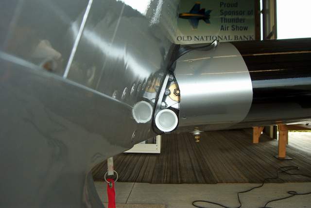
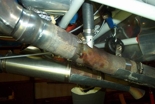
 6-18-05: It always bothered me that the exhaust pipes stuck out in
the breeze... so I cut them off with a cutoff disk. The exhaust tone
didn't change much, but does seem slightly less "sharp".
6-18-05: It always bothered me that the exhaust pipes stuck out in
the breeze... so I cut them off with a cutoff disk. The exhaust tone
didn't change much, but does seem slightly less "sharp".
5-25-05: I finally got around to checking the wheel alignment with the plane completely finished. I had done the alignment during construction by following Mark's instructions as best I could.
With the tail down, full fuel, no pilot or pax, and no extra weight added, the alignment was toed-in about 2.5 degrees (if I did the math correctly). The raw numbers were 2.25" toe-in (per side) when measured against a 51" long straight edge. I used a straight edge on each wheel and measured the front and rear edge separation. Easy stuff.
 Here you can see one of the simple straight edges used. It is clamped to
the brake disc.
Here you can see one of the simple straight edges used. It is clamped to
the brake disc.
 A closer look.
I added one of Mark's shims to each side. After adding the shims, the camber was reduced (good) and the 2.5 degrees toe-in changed to 0.8 degrees toe-out.
Bob Japundza and I have a running debate over whether a little toe-in or a little toe-out is better. I searched the web and found that there seems to be no consensus on which is better. I say toe-in, Bob says toe-out. Since this is my website, I could post a bunch of crap about why I am always right, but the bottom line is that straight is best.
I can say that the original alignment would cause the tires to squeak loudly when rolling on smooth concrete. The new alignment also causes the tires to squeak, but not as loudly. Time will tell if the tires wear any better, but I suspect that they will do better.
As far as ground handling, I can tell no great difference between the two alignments, although during the limited time that I've flown it this way, the toe-out seems more squirrelly.
5-3-05: I just returned from Piqua, OH, home of Hartzell Propeller. It was a fabulous trip. No, I don't get anything to say this stuff�. but to say that I was impressed would be a gross understatement.
A little background first, I bought a new Hartzell two blade from Mark for my bird. Oddly, after 22 hours it developed a minor grease leak. Since it was still leaking 10 hours later, I thought I should check on it.
I called Hartzell and they said "Bring it over and we'll fix it." No hassles, no grilling questions, no evading, no delays. They were very accommodating of my schedule even though I told them that it was not an emergency since I fly for fun and have no set schedule.
I asked if we (John Crabtree went with me) could see the repair process since we were curious (clueless, really) about what is inside of one of these props. Not only did we get to see the overhaul facility, we got a tour of the manufacturing facility too. More about those later.
I also wanted to get a dynamic balancing while I was there. WOW! Does that make a huge difference! I didn't think my vibration level was bad, but now it is very smooth. To say that I am pleased would also be a gross understatement. It's worth every penny of the approximately $180 cost�. chump change in aviation dollars. HIGHLY RECOMMENDED regardless of what you're swinging up front.
John and I had arranged to arrive on Sunday morning. Even though those are not regular business hours, there were several people around. We were greeted like we were the most important people on earth, not like we were interrupting their weekend� which we were! After we put the planes in the Hartzell hangar, John and I hopped in the airport car and spent the rest of the day at the Wright-Patterson AF museum. WPAFM is a great museum. And it's free! Where else does the government give you anything worthwhile for FREE?
The next morning we arrived back at the Hartzell hangar. My prop was already well along in the repair process so after checking on it, we hopped back into the company car and went to see one of the four Hartzell facilities in Piqua. We went to the facility that manufactures metal props. On the way to the facility, I got into the wrong lane, a turn lane. A Hartzell employee on her way to work spotted the airport car and knowing where we were supposed to be going, motioned for us to follow her. Now, that's customer service!
We arrived at the metal prop production facility, a state of the art operation to say the least, and met John Popel, a tech rep. John gave us some safety glasses and off we went. We saw everything. It was amazing. It's simply beyond my ability to type it all. If you are impressed by industrial equipment and appreciate the art that goes into producing a product, this is a must-see facility. John Popel had an amazing grasp of the minutest details and you could tell he is the kind of guy who is excited to go to work every day. John said that cameras were allowed in almost all areas� and wouldn't you know it, I didn't bring one along!! DOH! John said that a facility tour can be arranged for small groups easily. This would make a stupendous EAA chapter event. I learned more about props in 2 hours than I have in the last 20 years.
While at the production facility, we also got to talk to Les Doud, a propeller integration engineer. Les also was a wealth of useful information. John and I asked him 500 questions. I asked if Hartzell had a job opening for me. LOL.
Les explained to us what to look for in a prop, what was good, and what was bad. We tried to get some info on what products were in the pipeline and told them that we wanted a 25# prop with better performance� and it needed to cost less than $1000� and last forever. Les and John had every reason to whack us on the head, but instead simply said that they were working on it. LOL! Seriously, after seeing the effort that they put into their prop design, production, and service I almost felt guilty for paying as little as I did for mine.
Crabtree and I headed back to the airport to see how my grease leak repair was coming along. When we arrived my prop was being rolled out to the Rocket. We inquired what, if any, problems were found. Everything looked OK was the reply. Mark, the lead mechanic, explained that occasionally a grease zerk check ball will dribble a little bit, or some of the petroleum distillates will escape from the grease with weather changes, age, etc., or it might have simply had a bit of stray grease get past the O-ring. I was happy to hear that nothing was wrong. It's very comforting to have THE experts look over your installation and say "Looks fine."
While Mark was putting the prop back on the Rocket, John and I took the full tour of the overhaul facility. Steve Reindel showed us around the overhaul shop, which was a miniaturized version of the factory, with many of the same capabilities. Steve explained that Hartzell had overhauled their overhaul procedures, so to speak, so that they could beat the overhaul business competition is all categories: price, quality, and turnaround time. Seeing as how they got my prop in and turned around in just a few hours� I believe him! Although my prop was covered under warranty, the price Steve said I would have paid otherwise was quite reasonable� on the order of a few hundred dollars for the entire inspection, repair, and reinstallation. Wow!
In summary:
1) Hartzell service rocks! (No, they didn't pay, coerce, or bribe me to say it.)
2) My teeny-weeny problem was given more attention than Air Force One probably gets.
3) Hartzell gives a great tour. Unbelievably informative. Highly recommended.
4) The cost was minimal. In airplane dollars, it was chump change for the entire trip.
5) My prop was inspected and installed by experts�. Priceless.
Other trivia:
6) Never put more than 6 pumps of grease (1 ounce) into your prop during service, usually at annual. Use the proper grease. Make sure you take the opposite zerk out so you don't push grease past the seal. I didn't do any of these things since I haven't had to service my prop yet, but it must be a common user error because we heard it mentioned several times.
7) We also got to go to the air force museum� too cool. If you've never been there� why the heck not?
Vince
4-21-05: I've got 34 hours on the Rocket now. I feel compelled to discuss my impressions.... I just can't keep my yap shut and it's a slow day at work. ;-)
The Rocket is sensitive to changes in CG (duh!). Jim Anglin, who is 99% ready to fly his Harmon, asked me about this topic. Here's my impressions:
Solo with nothing in the back: Up elevator at slow speeds is quite heavy. I readjusted the elevator trim travel to get more nose up. It helped but it's still heavy. Coming in to flare, you really have to pull to get a decent flare. Maybe I should do some Bowflex bicep training. It wants to naturally wheel land under these conditions and it's easy enough to do. It naturally likes to be rather tail high and I really don't get all warm and fuzzy about the possibility of nicking the prop. Would it? I can't say for sure... but I think the answer would be "Probably" since even on rollout it still feels nose heavy. It is easier to keep trimmed while in the air though.... I think that would be the forward CG "lawn dart" effect.
Solo with 45# in the baggage: Sweet. Flies nice. Moderate stick forces when slow. Trims OK at cruise. Your choice of landing technique... both will be bouncy until the gear gets done horsing around... just wait for it to stop. I'm told by ground observers that nothing unusual is visible, but it feels like you're landing a pogo stick on all but the most perfect touchdowns.
Me and 220 pounds of lard butt in the back seat: Full stall landings work fine. Less bouncy-bouncy due to the lard. Trim at cruise gets to be pretty twitchy. Couple that with a plane that will climb like a banshee and you'll have fun trying to hold your altitude. Tell your passenger not to breath... it affects the trim.
So, what does this mean to you? I don't know. However, if I were getting ready to test fly a new Rocket I think I'd consider throwing a 50# sandbag in the baggage compartment from the start. I'd want to start the test flying in the middle of the CG range. My Rocket has an RV-4 tail. I suspect that the choice of tail would make some difference but I'm not going to speculate on the differences.
I've seen many different sizes of trim tabs on different Rockets. I suspect that they're all trying to optimize the trim forces at cruise -vs- slow flight. I'll go out on a limb here and say it would be optimal to have a trim tab on each elevator, one for cruise (small and very non-sensitive) and one for slow flight (a giant barn door sized tab). Hmmmm, I wonder what you'd get if you pushed 'em both opposite directions.......... well, maybe a good altitude hold autopilot would be better.
4-21-05: Spring flying. It's getting hotter out there. I've been anxious to see if my cowl/plenum/oil cooler will be able to handle the higher temps. Yesterday it was in the low 80s �F. Temps in the air are fine. CHT's of 350 to 370 �F at 2300RPM/20" while doing some nozzle tuning (leaning to GAMIfy them) were seen. Normal cruise CHT's are 350 - 360 �F. I can live with those numbers if they don't get ugly on hot summer climbouts.
Oil temps taxiing on the ground get warm quickly. Oil temps will shoot up to 215-225 �F very quickly. I participated in a poker run last weekend. Taxiing around shot the oil temps up PDQ, but they dropped quickly on the 20 mile hops between airports. Japundza says I need to install a fan under the oil cooler. Hmmmm, I'll have to consider that. In the mean time, I think I'll reinstall the "Cool Collar" on the oil filter and see if that makes a difference.
I might even consider a cowl flap or louvers later if things get out of hand. More later....
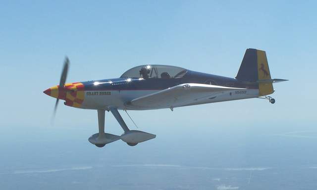
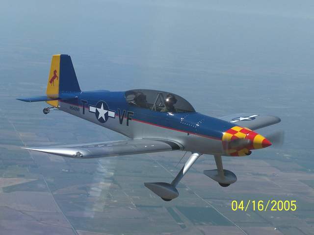 4-16-05: Terri Truitt takes great air to air shots. Wow.
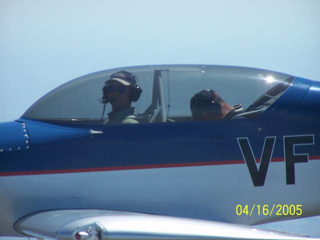 Here's my good friend, Keith McCutchan, during
his first Rocket trip.... sound asleep. No kidding.
Here's my good friend, Keith McCutchan, during
his first Rocket trip.... sound asleep. No kidding.
We'd gone to Lambert's in Sikeston, MO for lunch with a group of RVs. I guess the big lunch was too much for him. Well, at least he wasn't puking. So much for the thrill and excitement of riding in a Rocket.
 Power chart for Lycoming AEIO-540-C series engines.
Oil cooler door
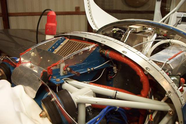 3-21-05: My oil temps were only reaching 150 to 160F
during flights when the OAT was less than 65F. I decided to install a
butterfly type oil cooler door inside the oil cooler plenum, shown here with the
cover removed. The butterfly door is made from a piece of aluminum rod,
nylon bushings, and a scrap of sheet aluminum. The only difficult part to
building this is that you need access to a milling machine to easily mill a flat
area on the rod so the sheet fits nicely.
3-21-05: My oil temps were only reaching 150 to 160F
during flights when the OAT was less than 65F. I decided to install a
butterfly type oil cooler door inside the oil cooler plenum, shown here with the
cover removed. The butterfly door is made from a piece of aluminum rod,
nylon bushings, and a scrap of sheet aluminum. The only difficult part to
building this is that you need access to a milling machine to easily mill a flat
area on the rod so the sheet fits nicely.
The lawn mower type push-pull control doesn't have enough fine control to keep the door positioned properly in flight. I plan to install a vernier type push-pull cable soon to correct that problem. Other than the cable problem, the door works very well. I am able to raise the oil temp by 50 F by closing the door.
4-3-05: I installed a vernier type cable and it works very well. Sorry, I don't have a picture of it.
 Door opened.
 Door closed.
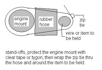 Someone asked how I made the
standoffs in the engine compartment. The purpose of the standoff is to
keep the wire or other item from chafing on the engine mount or other structure.
If you don't like zip-ties, you can do the same thing with waxed cord.
It's a good idea to put something between the zip-tie and the painted surface of
the engine mount since the zip-tie will eventually dig into the paint.
Someone asked how I made the
standoffs in the engine compartment. The purpose of the standoff is to
keep the wire or other item from chafing on the engine mount or other structure.
If you don't like zip-ties, you can do the same thing with waxed cord.
It's a good idea to put something between the zip-tie and the painted surface of
the engine mount since the zip-tie will eventually dig into the paint.
Electronic Ignition
2-2005: I had a mag problem after only 17 hours of flight time. I decided that this would be a good excuse to add electronic ignition. I chose the Jeff Rose EI system. I chose this system mostly because Jeff has a timing housing that replaces the right magneto. The other option, mounting a magnetic pickup behind the flywheel, was not appealing to me simply because I did not want to remove the prop. YUCK!
 The timing housing replaces the right mag. Timing is set mechanically by
aligning the magnetic pickup with the 11th tooth on the pickup wheel inside the
housing while the engine is at TDC. It is pretty easy.
The timing housing replaces the right mag. Timing is set mechanically by
aligning the magnetic pickup with the 11th tooth on the pickup wheel inside the
housing while the engine is at TDC. It is pretty easy.
The rubber magneto pads, standard Lycoming parts that go between the mag and the gears inside the accessory housing, are one pesky item. They tend to misalign themselves when you install the magneto or the EI timing housing. I use a blob of grease on the back of the pad so they don't fall out of place while installing the timing housing.
I also had to trim one of the mag clamping studs down a bit. It was preventing the timing housing from rotating into proper position.
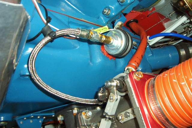
 I mounted the ignition coils on the firewall step. Works great.
 Installing the ignition wires is very straightforward. You do have to be
careful when cutting the wires to length. The wire for the #2 cylinder was
barely long enough... I should have cut it first!
Installing the ignition wires is very straightforward. You do have to be
careful when cutting the wires to length. The wire for the #2 cylinder was
barely long enough... I should have cut it first!
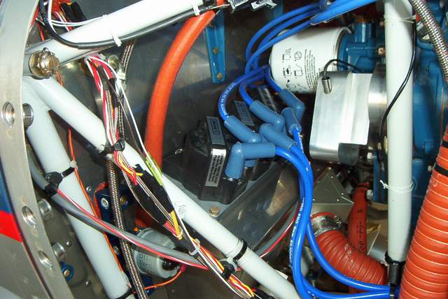
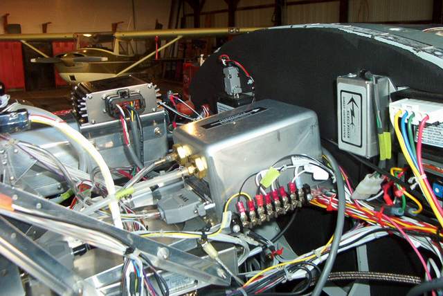 The XDI control box and the manifold pressure sensor mounts behind the firewall.
The XDI box is visible at the upper left , mounted on top of the glove box.
The MAP sensor is the small box mounted on the upper right, just left of the
wig-wag box with the colorful wires.
The XDI control box and the manifold pressure sensor mounts behind the firewall.
The XDI box is visible at the upper left , mounted on top of the glove box.
The MAP sensor is the small box mounted on the upper right, just left of the
wig-wag box with the colorful wires.
 Jeff Rose uses 8mm automotive wires. Since I was using Autolite UREM37BY
plugs, which are supposedly good for more horsepower than the more commom
UREM40E plugs, Jeff provided adapters. The adapters are simply a brass
nut, a 3/16 slice of rubber hose to provide a "bite" on the wire, and the little
springlike contact piece. They are very easy to assemble. The
contact piece slides in next to, but not into, the spiral core of the plug wire.
Jeff Rose uses 8mm automotive wires. Since I was using Autolite UREM37BY
plugs, which are supposedly good for more horsepower than the more commom
UREM40E plugs, Jeff provided adapters. The adapters are simply a brass
nut, a 3/16 slice of rubber hose to provide a "bite" on the wire, and the little
springlike contact piece. They are very easy to assemble. The
contact piece slides in next to, but not into, the spiral core of the plug wire.
I was able to run the engine last night. I hope to do some flight testing soon. The system is setup to start using the left mag and the EI turned off. After starting with the impulse mag, the EI can be turned on. The reason for this is that a few instances of kickback have occurred when using the EI to start. Mostly by people (like me) who have Skytec starters. Jeff says that you can use the EI to start if you get the engine spinning before you turn on the EI. I'll worry about trying that later after the system proves itself.
The engine idles at 670 RPM on the mag only. Flipping the EI on raises the RPM to 790. Idle is definitely smoother with the EI. The results were the same at higher RPMs .... on the ground. Flight test results will be reported on later!
2-28-05: I have made several test flights now. There are some issues regarding the MAP sensor giving too much timing advance, so it is shut off for the moment.
3-14-05: After much tweaking and testing, I finally gave up and reinstalled the right magneto. I simply could never get the in-flight, smooth running engine that so many others had claimed. I don't have any firm answers why, though I blame either the magneto replacement timing housing, myself, or the new generation of coils and controllers from Electromotive. Jeff Rose did everything he could to help me, but I just couldn't get it to work on my plane. YMMV!
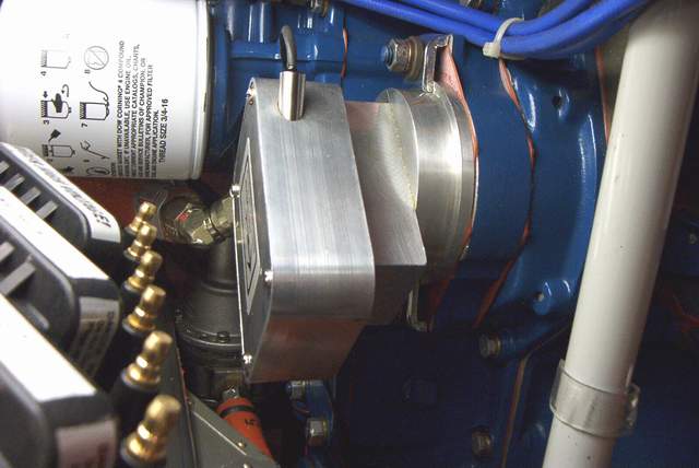
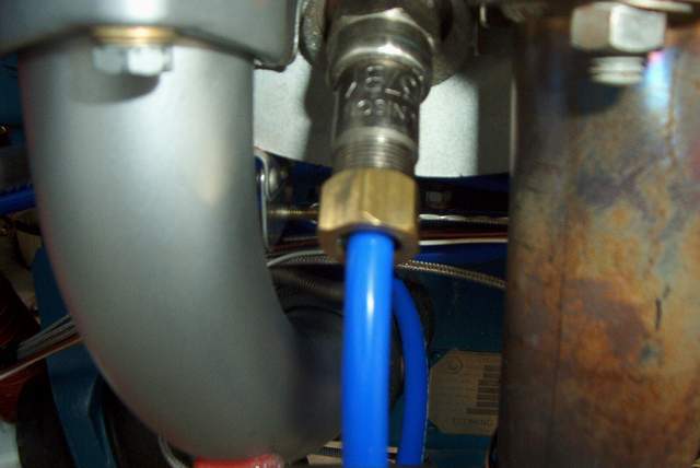
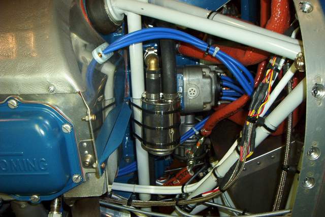
 The installation of the electronic ignition prompted me to move a few fuel lines
that I wasn't happy with. Previously the fuel pressure line came off of
the engine driven pump and the sensor was on the firewall. The hose was
much longer than I liked. Don Rivera of Airflow Performance has a 90
degree restrictor fitting that mounts on the throttle body near the fuel line.
As you can see in the photo, the pressure line can be made much shorter now.
The installation of the electronic ignition prompted me to move a few fuel lines
that I wasn't happy with. Previously the fuel pressure line came off of
the engine driven pump and the sensor was on the firewall. The hose was
much longer than I liked. Don Rivera of Airflow Performance has a 90
degree restrictor fitting that mounts on the throttle body near the fuel line.
As you can see in the photo, the pressure line can be made much shorter now.
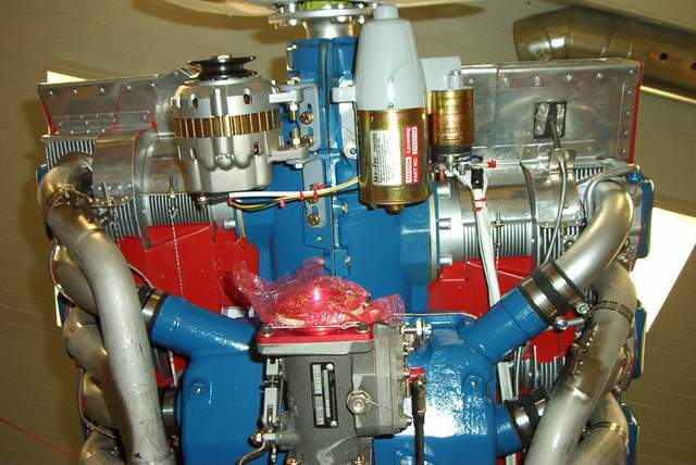 February 2005:
A buddy, Jim Truitt, has an RV-8 that uses the same Landoll alternator and
bracket that I had. His bracket broke and destroyed the alternator and all
three brackets! Yikes. Fortunately the engine wasn't harmed.
February 2005:
A buddy, Jim Truitt, has an RV-8 that uses the same Landoll alternator and
bracket that I had. His bracket broke and destroyed the alternator and all
three brackets! Yikes. Fortunately the engine wasn't harmed.
Landoll's brackets are painted gray (see mine in the photo above). It turns out that the gray paint was to cover the chromed piece of bar stock that Landoll made the brackets from. Yikes! CHROME! Not on my airplane. Even worse, he used a torch to bend and cut the slots. Indeed, the paint was hiding some serious crap! You could see the tiny stress cracks with your naked eye after stripping the paint off.
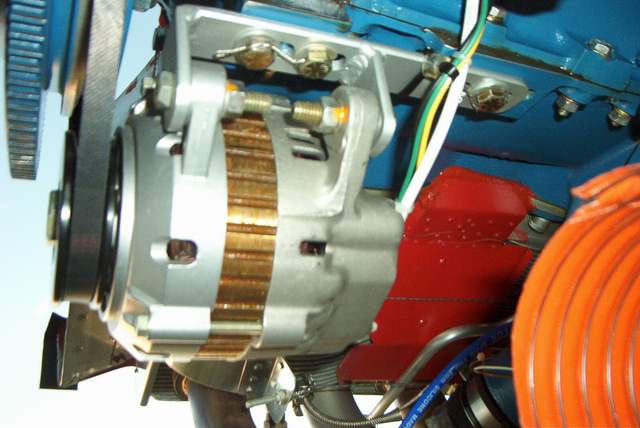 I made a new one-piece bracket from mild steel. It should last the
life of the plane!
I made a new one-piece bracket from mild steel. It should last the
life of the plane!
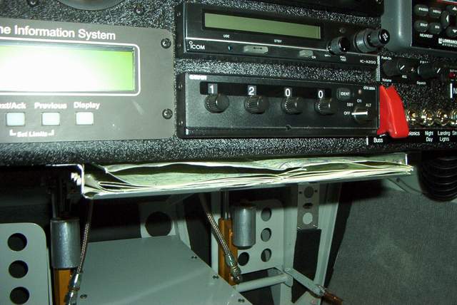
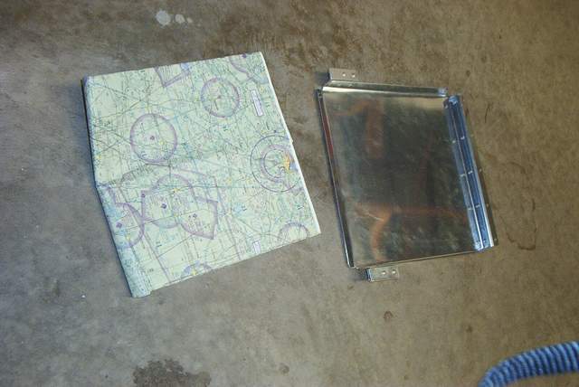 December 2004: The coolest map tray ever.
 The tabs allow it to mount to the aft edge of the instrument panel without any
fasteners. The aft edge (the left side in the picture) simply gets tied to
whatever is convenient under the panel. I used some waxed cord to tie it
to the radio tray.
The tabs allow it to mount to the aft edge of the instrument panel without any
fasteners. The aft edge (the left side in the picture) simply gets tied to
whatever is convenient under the panel. I used some waxed cord to tie it
to the radio tray.
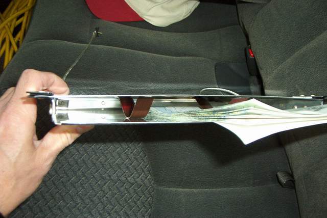
 A folded map just sits there, conveniently placed where you can see it, but it's
not on your lap or on the floor flopping around. The map doesn't interfere
with the stick travel ... unless you're doing outside loops.
A folded map just sits there, conveniently placed where you can see it, but it's
not on your lap or on the floor flopping around. The map doesn't interfere
with the stick travel ... unless you're doing outside loops.
 When you want the map out of sight, just push it on into the tray.
 Here's an easy way to install it... unless you're smart enough to do it while
building or if you remove the boot cowl. This was faster.
Here's an easy way to install it... unless you're smart enough to do it while
building or if you remove the boot cowl. This was faster.
 1-31-05: OK, I temporarily removed my map tray because
there were a couple of minor problems with the map tray: 1) the tray did not
have a top, which occasionally allowed a map to snag the bottom of the radios
above it 2) the Rocket accelerates so fast on takeoff that the maps would fall
out into my lap.
1-31-05: OK, I temporarily removed my map tray because
there were a couple of minor problems with the map tray: 1) the tray did not
have a top, which occasionally allowed a map to snag the bottom of the radios
above it 2) the Rocket accelerates so fast on takeoff that the maps would fall
out into my lap.
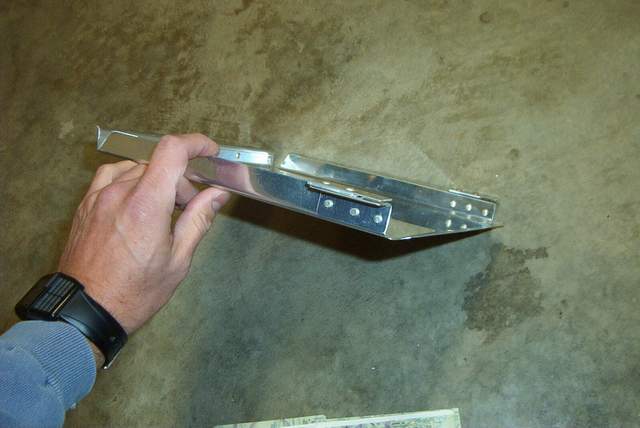
I added a top. No problems there.
To cure the problems with the maps falling out during acceleration, I could have simply added throttle more slowly... BWA HA HA HA HA HA HA..... I make myself laugh out loud sometimes. Since slower acceleration is NOT an option, I added the two spring steel straps you see inside the tray. Only one end is fixed. The other end is free to compress as you add stacks of maps. Works very well. BTW, the spring steel straps are simply made from strapping left over from one of my Van's crates.
As you can see in the picture, the map slides under the strap and the strap gives enough friction to keep it in place.
I also added tinnerman nuts, etc. so that I can install or remove the tray easily.
 December 2004:
Strafing a train. The train is actually much closer than it appears.
December 2004:
Strafing a train. The train is actually much closer than it appears.
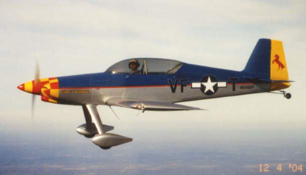 12-04-04: John Crabtree snapped these great shots. Yes, I'm gonna
have them enlarged to hang on my wall.
12-04-04: John Crabtree snapped these great shots. Yes, I'm gonna
have them enlarged to hang on my wall.
 Cool picture. Now I need someone who can fly upside down to get a shot
from above.
Cool picture. Now I need someone who can fly upside down to get a shot
from above.
 It looks like my wife, Tammy, is going to get a ride. Nope. The test
time is not over yet. She only got to sit in the back while I taxied from
the gas pump to the hangar.
It looks like my wife, Tammy, is going to get a ride. Nope. The test
time is not over yet. She only got to sit in the back while I taxied from
the gas pump to the hangar.
 We put this shot in with our Christmas cards.
 Oil separator made from a brand new Oatey PVC cement can. I threw away the
PVC cement just to get the can. Drill a couple 1/2" holes and solder on
the brass hose barbs.
Oil separator made from a brand new Oatey PVC cement can. I threw away the
PVC cement just to get the can. Drill a couple 1/2" holes and solder on
the brass hose barbs.
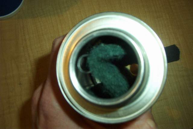 Before I soldered on the hose barbs, I pressed a short length of aluminum tubing
into one of them. You can see it on the left. A piece of Scotchbrite
pad between the two openings will catch the oil vapors.
Before I soldered on the hose barbs, I pressed a short length of aluminum tubing
into one of them. You can see it on the left. A piece of Scotchbrite
pad between the two openings will catch the oil vapors.
 Installing it on the plane. Don't forget to include a whistle slot in the
hose near the engine fitting.
Installing it on the plane. Don't forget to include a whistle slot in the
hose near the engine fitting.
 Temporary Zip ties until I can get a couple of clamps.
 The outlet is placed right next to the exhaust pipe to burn off any vapors that
might escape.
The outlet is placed right next to the exhaust pipe to burn off any vapors that
might escape.
I tried to burn the vapors off without the separator can, but their was enough oil that didn't burn to warrant the installation of the can.
The new can works great. However, I thought that a larger can would make even less back pressure on the system and catch more oil vapor, so I installed an even larger one. As far as I can tell it works very well.
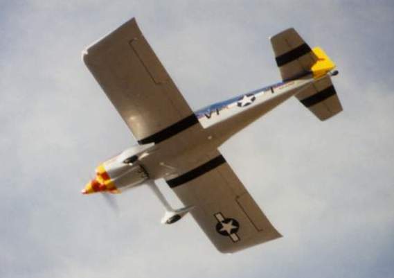
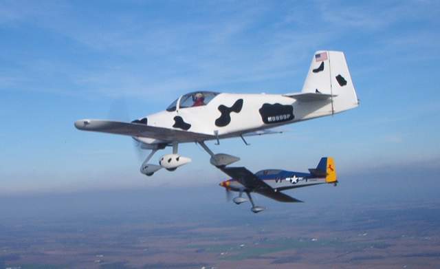 11-28-04: Me, Wayne Ray in the Cowbird, and John Crabtree in his
RV-6 cameraship somewhere over the scenic mountains of southwest Indiana.
11-28-04: Me, Wayne Ray in the Cowbird, and John Crabtree in his
RV-6 cameraship somewhere over the scenic mountains of southwest Indiana.
11-29-04: I had problems with oil pressure. First it was too low. I replaced the spring with the next heavier one and then the OP was too high when the oil was cold. It turns out that someone had cut the original spring down a bit and we didn't catch that during the overhaul.
Well, in my defense, the dimensions for those springs aren't exactly common and they're not in the OH manual.
So, I bought a new spring of the same weight as the original and all is good now after tweaking it with a few washers.
DATA:
original, shortened spring 61084: oil pressure at cruise 50psi
white spring LW11713: oil pressure at cruise 115psi, somewhat lower as the oil warmed fully.
new spring 61084 with 1/ 2 plain washer added under the spring: oil pressure at cruise 70 to 75 psi
new spring 61084 with 2 1/2 plain washers added under the spring: oil pressure at cruise 85 to 90psi
I could have probably just added washers to the first spring, but who wants a crappy spring doing this important job when the new ones are only $10 bucks.
FWIW, new Lycomings have an adjustable relief valve and you don't have to mess with the springs and washers.
Vince
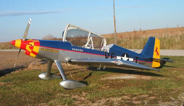
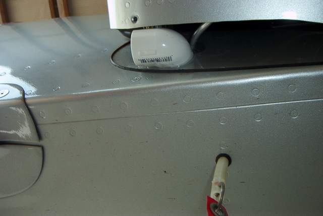
I flew N540VF without wheel pants or GLFs for several hours. The plane flew perfectly straight, ball centered, etc. I attribute this to 10% skill, hard work and sweat and 90% to good luck!
After I installed the pants and fairings, the left wing was slightly heavy. DOH! I attribute this to 10% skill, hard work and sweat and 90% to bad luck! The problem was unrelated to fuel loading, etc.
I had considered hoisting the plane up off its gear and getting out the strings, levels and lasers to figure out what the heck was misaligned. If it had rained yesterday, I would have done exactly that. I would have spent hours screwing around with it.
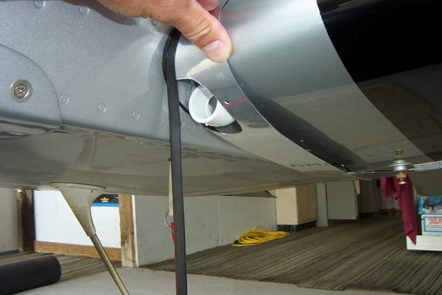
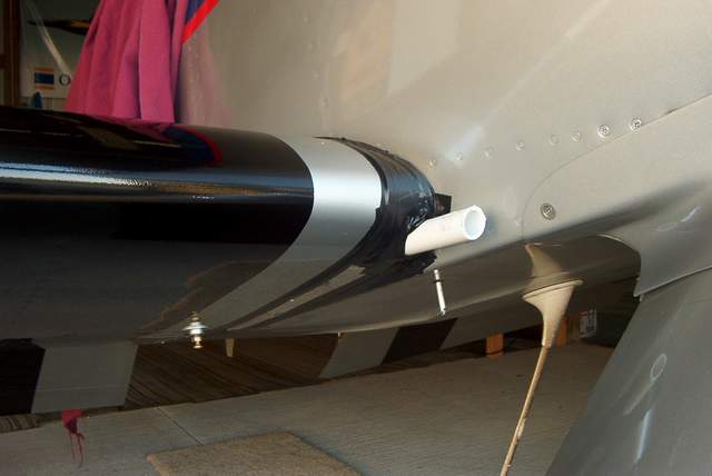
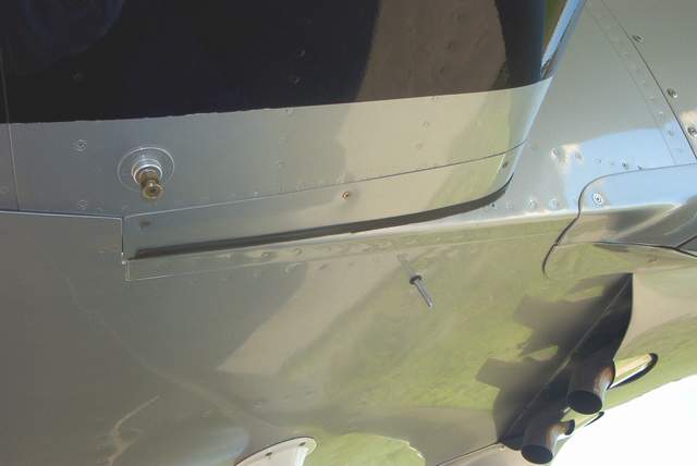
But yesterday was sunny and there was flying to be done. Seeing that my LGIFs had a small 1/8" to 1/4" gap in the trailing edge, I decided to tape them more tightly closed. This was just on a whim. I didn' t expect it to make any difference. BUT IT DID! The left wing heaviness was gone! It was back to the straight flying plane that it was before. WOO HOOOO!!
Now I just need to replace the ugly black electrical tape I used with something that matches the paint. I think I'll use that paint protection film that I've fallen in love with.
 This picture shows the offending gap. The other side was slightly worse.
Hey, go figure! I'm much happier now. Vince
 11-23-04: More data and observations. I've got 10.1 hours on her
now. The engine break in seems complete as temps and oil consumption are
stable. Several cross country hops are showing a consistent 235+ mph
groundspeed at 24 squared. I'm still calibrating the fuel flow so I
don't have a good number for that yet.
11-23-04: More data and observations. I've got 10.1 hours on her
now. The engine break in seems complete as temps and oil consumption are
stable. Several cross country hops are showing a consistent 235+ mph
groundspeed at 24 squared. I'm still calibrating the fuel flow so I
don't have a good number for that yet.
The pants and fairings were good for an extra 15 mph +/- but now I have a slight roll to the left. DOH! I'll have to figure that out and tweak it back in line.
I've added a few creature comfort items like a strap to hang my headset on so it's not on the floor when I get it. I also covered part of the glare shield with dark gray vinyl to eliminate an annoying glare.
I'm still carrying 5 gallons of water in the baggage compartment. I haven't figured out quite what to do about that. The CG numbers tell me I need 23 pounds of lead in the tail to maintain the current CG. I'd put some back there but I know that when I have a back seater that I'd be better off without the extra weight. It's a Catch 22. Perhaps a movable lead weight or a tank of water that can be drained?
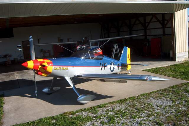
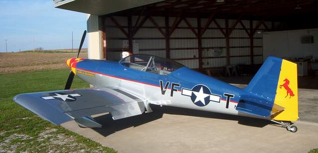 11-08-04: I finally got the wheelpants and GLFs installed.
WOW! It sure makes a huge difference in the appearance!
11-08-04: I finally got the wheelpants and GLFs installed.
WOW! It sure makes a huge difference in the appearance!
I don't have any good speed numbers yet... she's still a baby and breaking in the engine and stomping bugs is taking precedence over getting flight data. In raw, totally unverifiable numbers, she would go 230 IAS without the pants and fairings. I'm seeing nearly 250 IAS with them installed. I DO NOT KNOW if the ASI is accurate or not... no clue whatsoever!!! Yes, I have a GPS, but I simply haven't taken the time yet to compare speeds, altitudes, and winds.
I can say that Mark is correct about this 2 blade quirk. At 24/24 at 5300' and about 70 degrees I was geting 210 IAS with no pants/fairings. Everything else stayed the same except I pushed the prop up to 2600 RPM and got exactly no increase in speed, but she did show that she was drinking faster. This was a quick and dirty test... YMMV!
What I can say for sure is that she is FAST! Climb is fantastic.
I can also say... and you might want to LISTEN UP... that she is NOSE HEAVY unless you put some weight in the baggage compartment. Right now I've got 5 gallons of water (42 pounds) in the main baggage compartment. It's barely enough IMHO. The plane is quite light on the tail on landing rollout. I guess what I'm saying is that it would seem to be a POOR IDEA to do anything that would move the CG forward. I know others have done just that, but I'm not going to do anything that jeopardizes that expensive fan up front. YMMV!
Everyone keeps asking me about vibration so I'll say it: "It's just fine. I can't imagine why I'd want a 3 blade prop." There. Quit asking. Now, I haven't flown behind a 3 blade... I might change my mind... but I just can't see it from where I sit.
Flight handling is superb. Solid as a rock. 2G turns bleed the speed off fairly rapidly. I haven't done anything remotely resembling acro (yet) due to the weight it the baggage compartment. Making dents in the fuselage is NOT on the test plan! Anything that points the nose down builds speed very rapidly... much more so than the fixed pitch RVs I've been flying. At least that's the impression that I get. Therefore, the descent for good a buzz job needs a little planning and power changes. But the zoom climb afterwards is a pants wetting experience for sure.
The manual trim works just fine now that I adjusted it to have more nose up travel than nose down. The manual flaps work great too.
Approaches seem very solid and easy. Getting too slow is the thing to watch for since the prop really acts as a giant brake when the RPMs slow down. Adding power quickly remedies the problem, however an engine failure at this point would be bad, very bad. Something to keep in mind. With that in mind, I've adjusted my approaches to be a bit higher than in an RV. The big prop slows you down PDQ as soon as you're over the fence. For example, last night I passed the fence a bit high and going 94 IAS instead of the usual 85 IAS. As soon as I pulled the rest of the power off it was like tossing out an anchor and I was stopped and turned around about 2/3 of the way down our 2400' strip. Not a short field landing by any means, but very comfortable. If I'd been in a fixed pitch RV that high and fast I'd have definitely gone around.
Landing on grass is a real snooze. Landing on pavement doesn't seem to be any worse than any other taildragger with the exception that you can't see diddly over the nose after the tail drops. Wheel landing do have a bit of an advantage here. I've not done a full stall landing on pavement yet. Full stall landings in grass seem to give a nice group of hops down the runway as the mains flail around. You can feel the tailwheel planted, but the mains take a little longer to stay down.
Well, more later... I'm tired of typing.
Vince
My newly installed wheel pants. These are Sam James pants that I had
fitted before I got my hands on a set of Mark's very nice wheelpants. In
the end, I was just too lazy and pressed for time to switch. I did get the
great pleasure of making my own LGIFs and UGIFs... yuck, no fun.
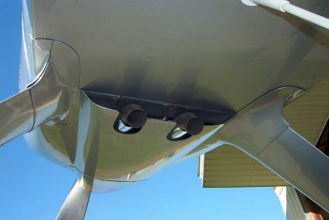
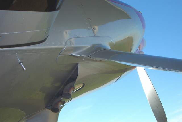 Here's a shot of the engine cooling air outlet. Before I installed the
pants and fairings this opening was much larger. Previously I had a 3/4"
spacer on each corner of the outlet. The spacer effectively made the
outlet MUCH larger. However, with the fairings installed it is impossible
to keep the larger opening.
Here's a shot of the engine cooling air outlet. Before I installed the
pants and fairings this opening was much larger. Previously I had a 3/4"
spacer on each corner of the outlet. The spacer effectively made the
outlet MUCH larger. However, with the fairings installed it is impossible
to keep the larger opening.
Time will tell if this is enough area to cool this beast in the hot weather. Yesterday the temps were about 65 degrees and the engine cooled OK.
There is a Catch 22 with these engines. One that I've not heard anyone discuss before. If you let the oil warm up to 95 or 100 degrees on the ground, then the CHTs are HOT on takeoff. Yesterday I saw 425 on the hottest CHT on climbout. The CHTs quickly settled at 325 to 350 during cruise flight.
So, do you warm the oil or just takeoff!? I do have an oil sump heater that I think I'll just make a habit of plugging in while I'm preflighting. At least that will warm the oil a little bit.
I also opened the inlet to my oil cooler a bit. I had been seeing oil temps of 210 max and decided that was a bit too high. I opened the cooler up a bit and yesterday the oil temp never got above 175. FWIW, I'm using the Positech cooler.
Here's a shot of the wing root fairings and fuel tank vent. You'll notice
that the tank support bracket doesn't show. It's hidden. Why doesn't
Mark do it this way????
Rich Winnick�s F1 Rocket
3268 W. 62nd Ave.
Denver, CO 80221
303-429-5213
My F1 Rocket is kit #2 and first flew in Nov. 2001. The engine is a C4B5 with 10:1 pistons, a modified cam, and a Rose electronic ignition firing the bottom plugs. The cylinders are Lycoming and were ported and polished, the case has had the aerobatic modifications by Divco, and all the internal parts were balanced. I�m using the Hartzell 2 blade prop and am happy with it�s performance. I normally cruise in the 2300-2400 rpm range and no complaints about the smoothness of the airplane so there are no immediate plans to change to a 3 blade prop. The plane has Christen inverted system and so far my gyros haven�t tumbled to the point of needing replacement. I did put in a full gyro panel with an ILS receiver but I don�t plan on doing much instrument flying until I put in a 2 axis autopilot. My Rocket went through some growing pains (failed engine mounts, leaking fuel tanks) but now has 280 hours and is a pleasure to fly. Flying locally in Colorado, mountain airports and density altitude don�t have much affect on the Rocket, the only problem is finding other airplanes that can keep up. Typical cruise is between 205-210 kts (4 hours to the West Coast, 6.5 to the East) and the wide CG allows golf clubs and plenty of bags to go along with your passenger. The paint on my Rocket is a 2 stage PPG and was done by Gene Kear in Colorado Springs. Another Rocket pilot, Ron Carter, was nice enough to forward some of his paint schemes to me which I used to come up with the final design. Thanks Ron, the plane sure gets a lot of attention on the ramp and there are already some other aircraft being painted with the same scheme. I hope all of you enjoy the Rocket experience as much as I do, give me a call to go flying or talk Rockets.
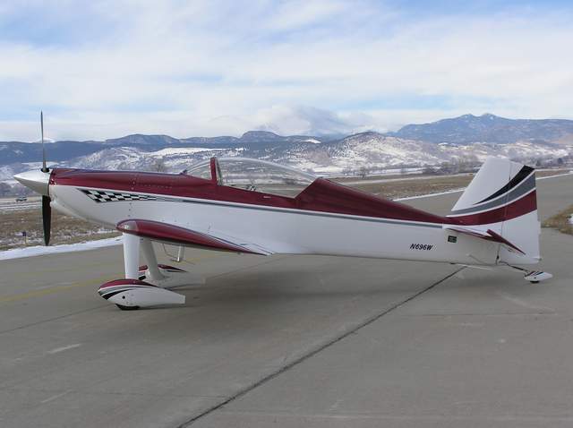
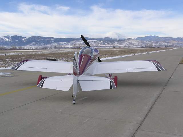
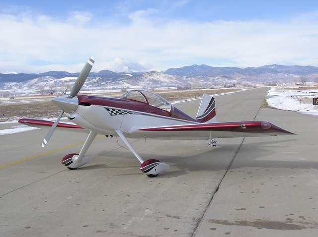

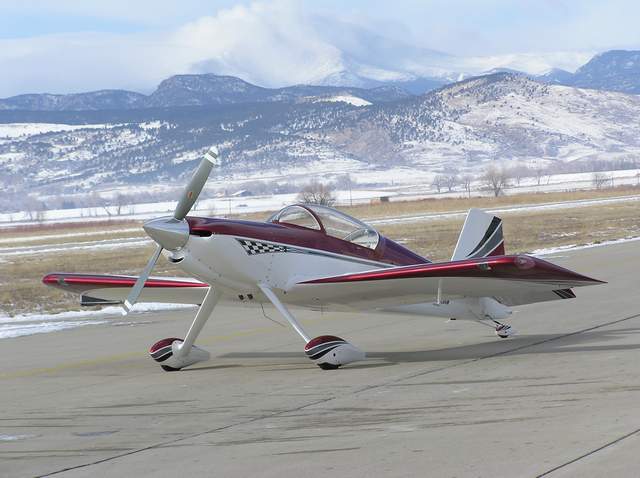
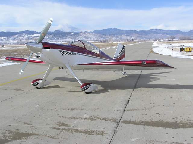
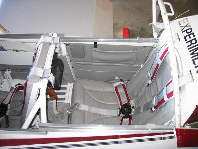
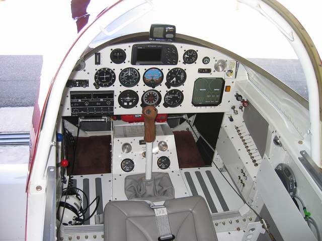
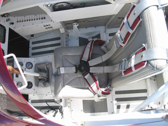
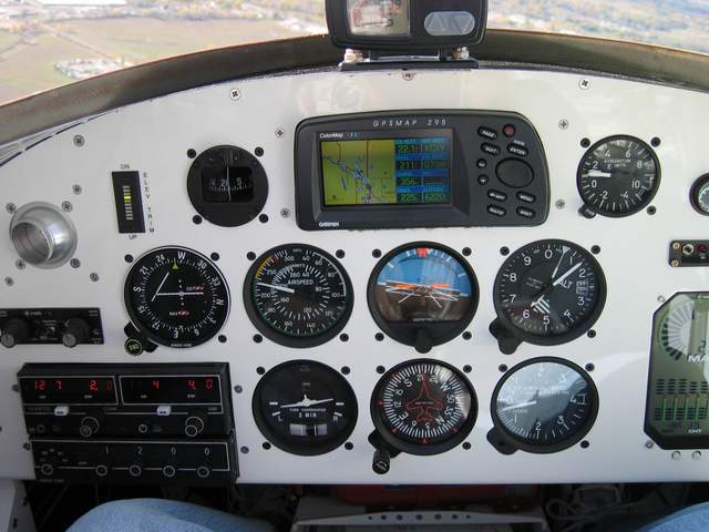
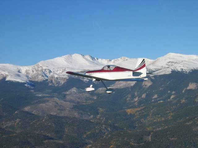
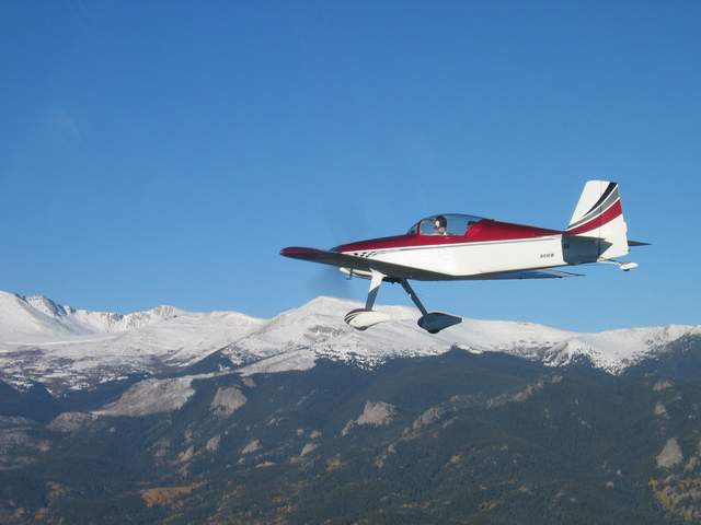
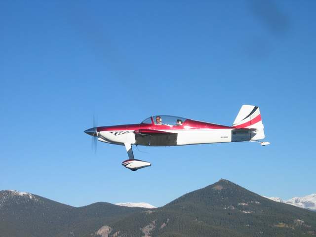
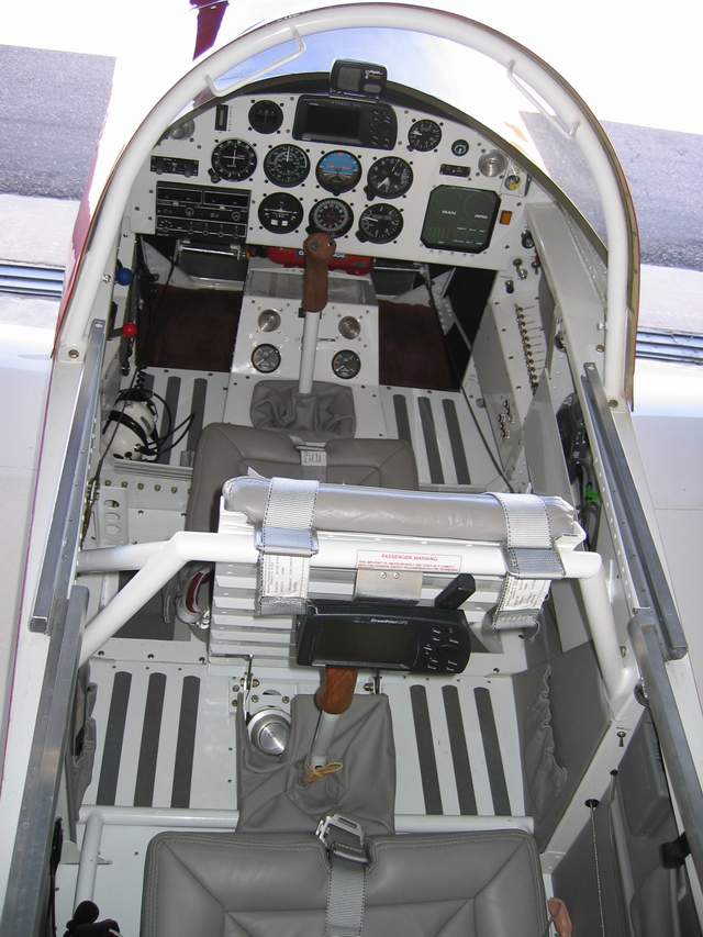
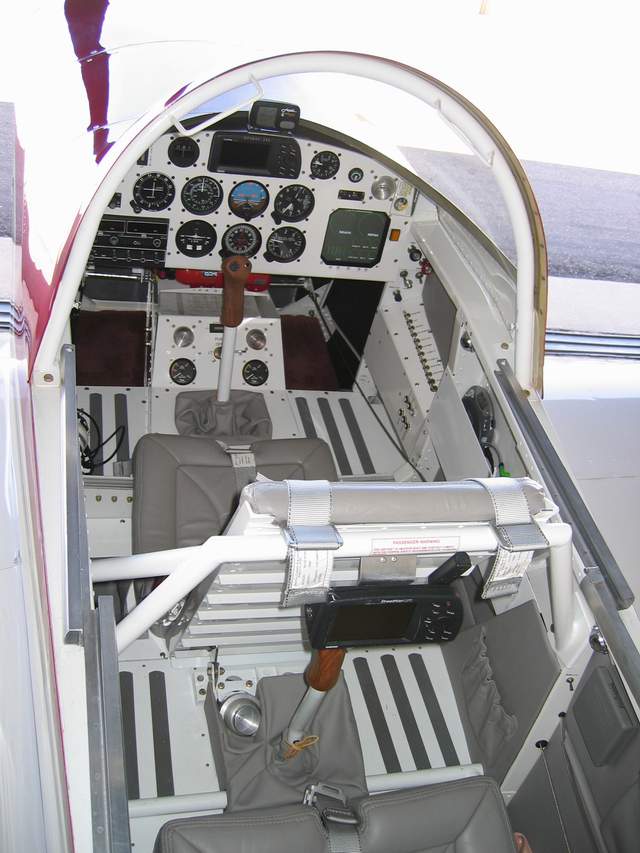
First Flight to another airport:
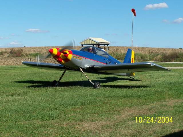 Finally, after days of rain, clear skies and favorable winds!
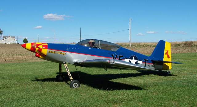 Full throttle! Well, not really, more like a smooth application of power.
By the time you get the throttle all of the way in, you're already airborne.
Do the same thing in a Cessna and you're barely moving!
Full throttle! Well, not really, more like a smooth application of power.
By the time you get the throttle all of the way in, you're already airborne.
Do the same thing in a Cessna and you're barely moving!
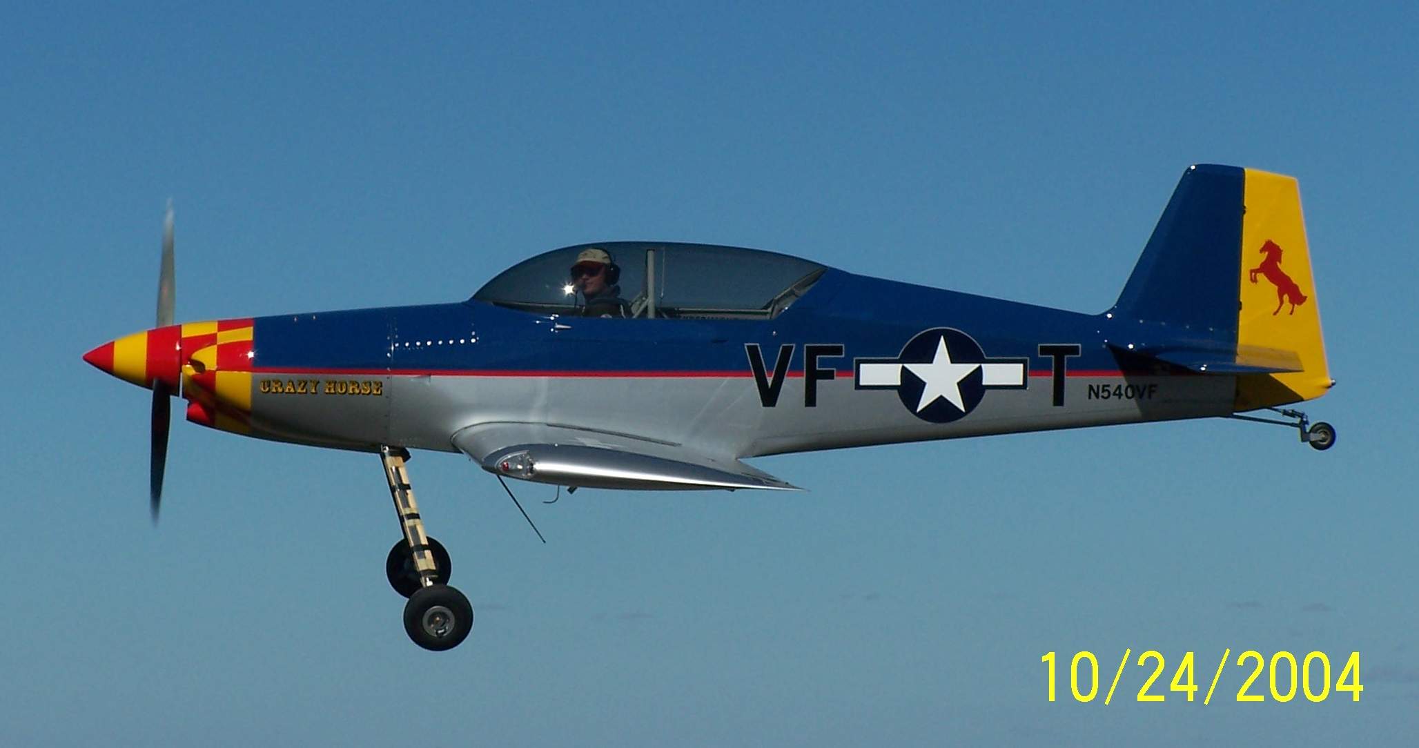 Terri Truitt took this beautiful shot from the back of husband Jim's RV-8A.
I gotta get those gear leg fairings and wheelpants put on!
Terri Truitt took this beautiful shot from the back of husband Jim's RV-8A.
I gotta get those gear leg fairings and wheelpants put on!
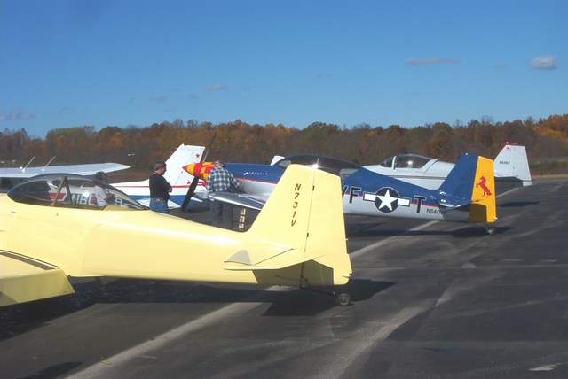 French
Lick airport, yes, that's really the airport's name, was the destination for
N540VF's first cross country flight. The airport sits on top of a large
hill with steep tree covered sides. Really gives you a bit of a pucker to
fly in here in a new plane.
French
Lick airport, yes, that's really the airport's name, was the destination for
N540VF's first cross country flight. The airport sits on top of a large
hill with steep tree covered sides. Really gives you a bit of a pucker to
fly in here in a new plane.
This was my first landing on pavement in N540VF. The plane behaved itself even though I made a tailwheel dragging, full stall landing which gives the main gear plenty of opportunity to bounce around. I have alternated between full stall and wheel landings. Either seems to work well, although I can certainly see where a full stall could develop into a pretty good bounce and a go-around.
The view over the nose, which is awful, makes for a much more interesting roll-out on landing. This alone is probably a very good reason to make wheelies. S-turning while taxiing is a must. I have given some consideration to getting some sort of booster seat to sit on while taxiing! ... but I'd have to also open the flopper canopy...DOH! Score one point for the sliding canopy!
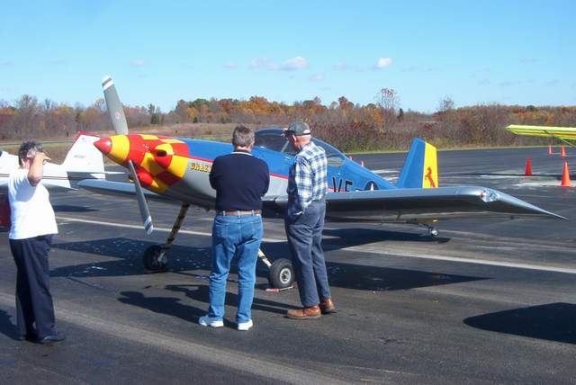 Jim Winings, on the right, also a Rocket builder, looks over my Rocket. I
can't recall the other folks names. Dang it. Jim poked all over the
plane, but didn't say much. I'll assume that he was overcome with awe and
not just being polite. ;-)
Jim Winings, on the right, also a Rocket builder, looks over my Rocket. I
can't recall the other folks names. Dang it. Jim poked all over the
plane, but didn't say much. I'll assume that he was overcome with awe and
not just being polite. ;-)
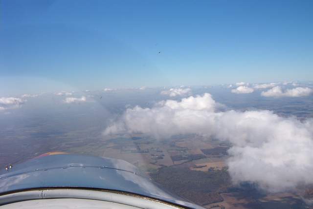 "Enemy planes at 1:00 low!" (He's in front of the large cloud, but you can't
really see him in the picture. The stuff above the horizon is just bug
splats.)
"Enemy planes at 1:00 low!" (He's in front of the large cloud, but you can't
really see him in the picture. The stuff above the horizon is just bug
splats.)
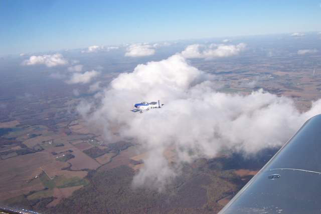 "Wait!
It's a friendly, albeit much slower, RV-8A!" I zig-zagged behind Jim
Truitt's very nice RV-8A on the way home.
"Wait!
It's a friendly, albeit much slower, RV-8A!" I zig-zagged behind Jim
Truitt's very nice RV-8A on the way home.
Return to the homepage:
http://www.vincesrocket.com/
Last updated: 03/25/10
CAUTION: This web site is not a publication of, nor approved by, Harmon LLC, Team Rocket, Van's Aircraft or any other person or entity listed herein, except me. Be advised that I am a blithering idiot with neither brains nor money and my advice is not to be trusted. So there. You have been warned! Vince